A bistable electrostatic switch

A bistable and electrostatic technology, applied in the direction of electrostatic relays/electro-adhesion relays, circuits, relays, etc., can solve the problems of poor shock resistance and vibration performance, large volume and weight, complex processing and packaging technology, etc., to improve the resistance to vibration and shock The effect of performance, small volume and weight, simple processing technology and packaging technology

Inactive Publication Date: 2017-01-18
CHINA AEROSPACE TIMES ELECTRONICS CORP
View PDF5 Cites 0 Cited by
  • Summary
  • Abstract
  • Description
  • Claims
  • Application Information

AI Technical Summary

Problems solved by technology

[0002] Existing miniature bistable switches mainly use the magnetic field to provide rotation and steady-state holding torque. The movable electrode of the switch contains a magnetic field sensitive mechanism, the processing and packaging process is complicated, the volume and weight are large, and the instantaneous power consumption is high; the existing miniature electrostatic switch generally only has one Stable state, poor shock and vibration resistance, low product reliability
Neither of the above two types of switches can meet the all-round use requirements of light and small size, resistance to strong mechanical environment and high reliability under complex conditions such as launch and space environment.

Method used


Image

  • A bistable electrostatic switch
  • A bistable electrostatic switch
  • A bistable electrostatic switch

Examples


Embodiment 1

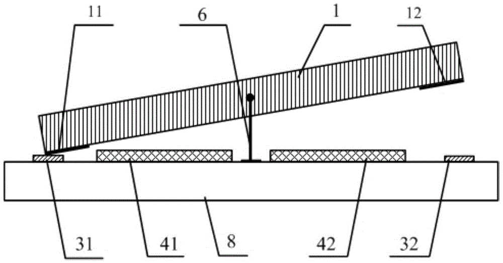
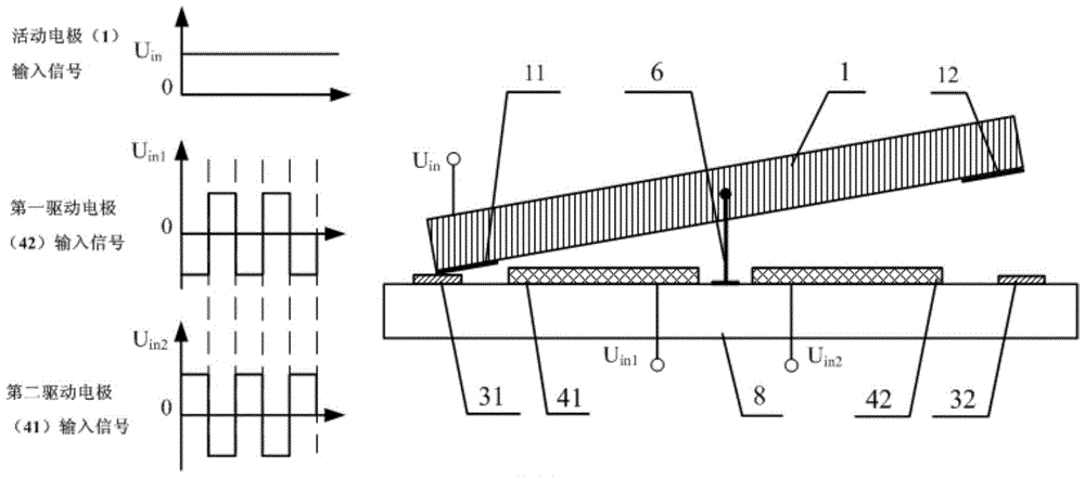
[0032] image 3 It is an embodiment of a unipolar active electrode bistable electrostatic switch, the polarity direction of the first drive electrode 41 and the second drive electrode 42 are opposite, and the active electrode 1 is connected to the external power supply U in connected. External power supply U in It is a power supply with fixed polarity, and the electrical signal U in1 and U in2 opposite polarity. such as U in is positive, then when U in1 positive, U in2 When it is negative, the active electrode 1 is flipped clockwise until the state is maintained; such as U in is positive, then when U in1 negative, U in2 When positive, the active electrode 1 still maintains a stable state. When U in is negative, then when U in1 positive, U in2 When it is negative, the movable electrode 1 turns counterclockwise around the support shaft or support axis until the state remains; in is negative, then when U in1 negative, U in2 When positive, the active electrode 1 st...

Embodiment 2

[0034] Image 6 It is an embodiment of a bipolar active electrode bistable electrostatic switch, wherein the polarity direction of the first active electrode 1a and the second active electrode 1b are opposite, and the first driving electrode 41 and the The second driving electrodes 42 are all connected to the external fixed power supply U in connected. Electrical signal U in1 and U in2 opposite polarity. such as U in is positive, then when U in1 positive, U in2 When it is negative, the active electrode 1 is flipped clockwise until the state is maintained; such as U in is positive, then when U in1 negative, U in2 When positive, the active electrode 1 still maintains a stable state. such as U in is negative, then when U in1 positive, U in2 When it is negative, the active electrode 1 flips counterclockwise until the state remains; when U in is negative, then when U in1 negative, U in2 When positive, the active electrode 1 still maintains a stable state. The switc...


PUM


Abstract

The invention provides a bi-stable electrostatic type switch. The bi-stable electrostatic type switch comprises a movable electrode, a first movable contact electrode, a first fixed contact electrode, a first drive electrode, a second drive electrode, a supporting frame and a substrate. The movable electrode is fixed to the supporting frame. The first movable contact electrode is attached to the portion, located on one side of a supporting point or on one side of the supporting axis, of the movable electrode. The first fixed contact electrode is attached to the position, where the projection of the first movable contact electrode is located, of the substrate. The first drive electrode and the second drive electrode are attached to the positions, where the projections of the two sides of the supporting point or the supporting axis are located, of the substrate respectively. The first drive electrode and the second drive electrode are connected to an external reverse circuit at the same time. The movable electrode is connected to an external power supply. According to the bi-stable electrostatic type switch, the size and the weight are small, the processing technology and the packaging technology are simple, and the bi-stable electrostatic type switch can be easily converted to engineering application. The bi-stable electrostatic type switch has two stable states, through a push-and-pull drive structure, the movable electrode is always kept in one stable state, and therefore the overall vibration impact resistance of an electrostatic type switch product is greatly improved.

Description

technical field [0001] The invention relates to an electrostatic switch, in particular to an electrostatic switch with bistable states. Background technique [0002] Existing miniature bistable switches mainly use the magnetic field to provide rotation and steady-state holding torque. The active electrode of the switch contains a magnetic field sensitive mechanism, the processing and packaging process is complex, the volume and weight are large, and the instantaneous power consumption is high; the existing miniature electrostatic switch generally only has one Stable state, poor shock and vibration resistance, low product reliability. The above two types of switches cannot meet the all-round use requirements such as light and small size, strong mechanical environment resistance and high reliability under complex conditions such as launch and space environment. Contents of the invention [0003] The technical problem solved by the invention is: to overcome the deficiencies ...

Claims


Application Information

Patent Timeline
Patent Type & Authority Patents(China)
IPC IPC(8): H01H59/00
Inventor 李慧娟杨子健孙建
Owner CHINA AEROSPACE TIMES ELECTRONICS CORP
Why Eureka
Try Eureka