Eureka AIR delivers breakthrough ideas for toughest innovation challenges, trusted by R&D personnel around the world.

A kind of igbt drive protection circuit

A technology for driving protection circuits and suppressing circuits, which is applied in the field of converters, can solve the problems of IGBT damage, long delivery period, and poor anti-interference performance, and achieve the effects of simple hardware circuit structure, short pulse suppression, and high reliability

Active Publication Date: 2016-06-15
GUANGDONG MINGYANG LONGYUAN POWER ELECTRONICS
View PDF9 Cites 0 Cited by
  • Summary
  • Abstract
  • Description
  • Claims
  • Application Information

AI Technical Summary

Problems solved by technology

[0003] At present, the solutions to the above-mentioned dead zone delay problem are as follows: 1. Use a dedicated integrated driver, but this kind of dedicated integrated driver has high price, long delivery period, and poor maintainability; 2. Use software control, but the software control has poor anti-interference performance. The IGBT is easily damaged after the software runs away or crashes

Method used


Image

  • A kind of igbt drive protection circuit
  • A kind of igbt drive protection circuit
  • A kind of igbt drive protection circuit

Examples


Embodiment Construction

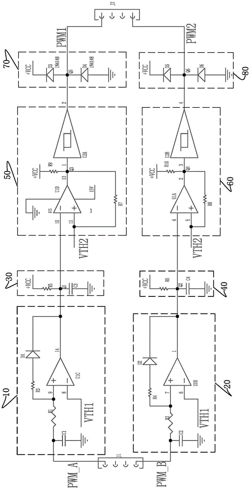
[0032] refer to figure 1 As shown, an IGBT drive protection circuit includes:

[0033] An input terminal J1, which receives two channels of PWM signals output by an external controller, and the two channels of PWM signals are marked as PWM-A and PWM-B;

[0034] An upper transistor short pulse suppression circuit 10, the upper transistor short pulse suppression circuit 10 includes a first capacitor C1, a first comparator U1C, a third resistor R3, and a first diode D1; one end of the first capacitor C1 is connected to the PWM- A signal terminal, the other end is grounded; the third resistor R3 and the first diode D1 are connected in series between the positive input terminal and the output terminal of the first comparator U1C, and the positive input terminal of the first comparator U1C is connected to the PWM-A signal A first resistor R1 is connected between the terminals, the negative input terminal of the first comparator U1C is the threshold voltage VTH1 input terminal, and ...


PUM


Abstract

The invention discloses an IGBT driving protection circuit which comprises an input terminal, an upper tube short pulse suppression circuit, an upper tube first-order circuit, an upper tube dead zone delay circuit, an upper tube clamping protection circuit, a lower tube short pulse suppression circuit, a lower tube first-order circuit, a lower tube dead zone delay circuit and a lower tube clamping protection circuit. The input terminal, the upper tube short pulse suppression circuit, the upper tube first-order circuit, the upper tube dead zone delay circuit and the upper tube clamping protection circuit are arranged between the input terminal and an output terminal, used for controlling an upper tube IGBT, and connected in sequence; the lower tube short pulse suppression circuit, the lower tube first-order circuit, the lower tube dead zone delay circuit and the lower tube dead zone delay circuit are used for controlling a lower tube IGBT and connected in sequence. By means of the IGBT driving protection circuit, a simple hardware circuit structure is adopted, short pulses are suppressed, upper tube dead zone delay control and lower tube dead zone delay control of the IGBTs are achieved, the diode clamping protection circuits are adopted for resisting interference, cost is low, and reliability is high.

Description

technical field [0001] The invention relates to a converter, in particular to an IGBT drive protection circuit for an internal power unit of the converter. Background technique [0002] When the converter is working, the upper IGBT and the lower IGBT on the same bridge arm inside the power unit cannot be turned on at the same time when driving, and when the upper and lower IGBTs are switched alternately, one IGBT is turned on and the other is turned off within the time There must be a certain dead zone delay. [0003] At present, the solutions to the above-mentioned dead zone delay problem are as follows: 1. Use a dedicated integrated driver, but this kind of dedicated integrated driver has high price, long delivery period, and poor maintainability; 2. Use software control, but the software control has poor anti-interference performance. The IGBT is easily damaged after the software runs away or crashes. Contents of the invention [0004] In order to solve the above tech...

Claims


Application Information

Patent Timeline
Patent Type & Authority Patents(China)
IPC IPC(8): H02M1/38H02M1/32
Inventor 付靖苏潮黄关烧陈铭薛小波黎裕文周立专孙文艺
Owner GUANGDONG MINGYANG LONGYUAN POWER ELECTRONICS
Why Eureka
Eureka Blog
Learn More