

Permanent magnet engine
A technology of permanent magnets and motors, applied in the direction of generators/motors, electrical components, etc., which can solve the problems of full application of mechanical energy devices
Inactive Publication Date: 2014-07-23
李浩东
View PDF0 Cites 2 Cited by
- Summary
- Abstract
- Description
- Claims
- Application Information
AI Technical Summary
Problems solved by technology
However, to date, devices that directly convert the magnetic energy of permanent magnets into mechanical energy are far from being fully utilized in practice
Method used
View moreImage
Smart ImageViewing Examples

Examples
Embodiment 1
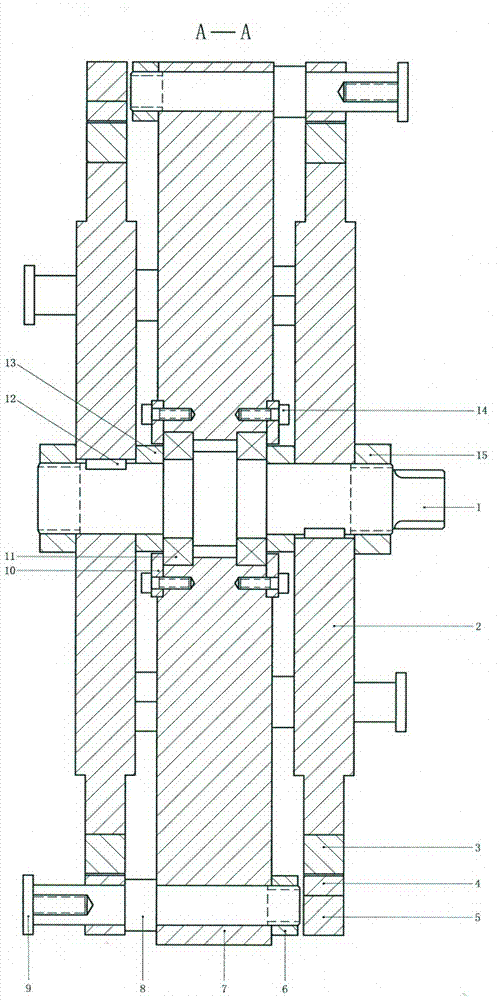
[0050] The positions between the stator and the rotor are interchangeable, but usually the stator is on the outside and the rotor is on the inside.
Embodiment 2
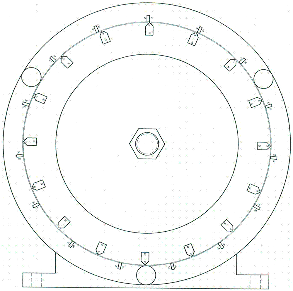
[0052] The positions of tangential permanent magnets and radial permanent magnets are interchangeable (see Figure 4 ).
Embodiment 3
[0054] In this embodiment, the tangential permanent magnets are installed on the stator, and the radial permanent magnets are installed on the rotor. In order to meet the needs of dynamic balance, 24 tangential permanent magnets and 25 radial permanent magnets are used (see Figure 5 ).
[0055] In an embodiment, the quantity ratio of the tangential permanent magnets to the radial permanent magnets may also be: 4:5, 8:9, 9:10, 30:32, 48:50, etc.
Login to View More PUM
 Abstract
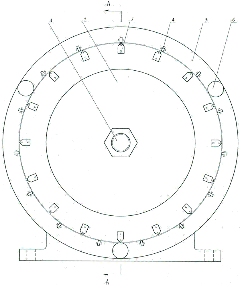
The utility model provides a permanent magnet engine. The permanent magnet engine comprises a stator and a rotor; the permanent magnet engine is characterized in that two groups of permanent magnets are arranged on the stator and the rotor, respectively, and each group of permanent magnets are evenly and circumferentially distributed at equal intervals; the magnetic poles of one group of permanent magnets are arranged tangentially and like poles face the same direction of rotation; the magnetic poles of the other group of permanent magnets are arranged radially and the ends of like poles are distributed evenly and concyclically. The permanent magnet engine has the beneficial effects of energy saving and environmental protection, simple structure, and being safe and practical; the permanent magnet engine is a mobile energy source and is capable of driving a generator to charge electric cars in 24 hours and supply power to industrial and agricultural production and lives of people.
Description
technical field [0001] The invention relates to a power output device, in particular to a device for converting the magnetic energy of a permanent magnet into mechanical energy. Background technique [0002] With the development of science and technology and the continuous improvement of people's understanding, the characteristics of using permanent magnets to do work without consuming their own energy have begun to be used by people, such as magnetic separators, magnetic levitation trains, magnetic levitation bearings, magnetic couplings and so on. According to the characteristic that the permanent magnet does not consume its own energy when doing work externally, in a sense, the magnetic energy of the permanent magnet does not obey the energy conservation. Permanent magnets have magnetic energy, using the magnetic energy of permanent magnets to save energy, reduce costs and simplify equipment structure, has been applied in the field of automobiles and motors. For ...
Claims
Login to View More Application Information
Patent Timeline
 Patent Type & AuthorityApplications(China)
IPC IPC(8): H02N11/00
Inventor李浩东
Owner李浩东