Engine System

a technology of engine and system, applied in the direction of valve details, valve arrangement, valve drive, etc., can solve the problems of fueling an automobile costing money, gas consumption at maximum power, and affecting costs, and achieve the effect of convenient opening

Inactive Publication Date: 2009-09-17
BILILIES THEODORE C
View PDF7 Cites 3 Cited by
  • Summary
  • Abstract
  • Description
  • Claims
  • Application Information

AI Technical Summary

Benefits of technology

[0011]The present invention achieves the intended effect of deactivating the fuel consumption of certain selected cylinders with the use of elliptical apparatuses that are placed in various positions over each selected valve. More directly, when the elliptical apparatus is placed above the intake valve in a horizontal position, it prevents the entrance of gasoline and thus results in no fuel consumption. Moreover, fuel is permitted to enter when the elliptical apparatus is placed in a vertical position. The elliptical apparatuses can be easily attached by someone possessing even the lower levels of engine mechanical aptitude through the use of solenoids. The elliptical apparatus is placed between the camshaft and the intake and exhaust valves. Typically, the elliptical apparatuses will be positioned so that half of the engine's cylinders would be actively working while the other half would be deactivated when full engine power is not needed. The elliptical apparatuses and solenoid installation is simple and cost efficient enough where they can easily be removed from the originally selected cylinder placement and switched in order to utilize each end of the engine evenly and avoid rapid deterioration that can be caused by using the same pistons all the time. In addition, the deactivation of the valves does not cause compression so there is no loss of force. The process of deactivation is seamless and can automatically allow full power at times such as acceleration when all cylinders are needed.
[0012]The present invention does not just apply to standard gasoline engines. Diesel and injection engines may differ in some aspects, but reap the same benefits when applied to the present invention. Injection engines are very similar to the carburetor engines. The difference resides in the fact that the carburetor engines use a manifold to supply fuel to all cylinders. The manifold is the connection between the carburetor and the cylinder. In order to achieve the substantial savings in fuel consumption as mentioned above, activating the elliptical apparatus of the present invention that are placed over the valves interrupts the fuel supply to provide the desired consumption results.
[0015]To deactivate the piston in relation to the present invention, a simple valve is placed in the pipe to redirect the fuel to another injector. This injector typically easily opens and returns the fuel back to the tank. Only one elliptical apparatus of the present invention is needed over the exhaust valve as the air that enters into the intake valve does not cause combustion due to lack of fuel and low compression.

Problems solved by technology

Even hurricanes have proven to affect costs.
In short, fueling an automobile costs money.
These engines typically come with 4, 6 or 8 cylinders that operate with opening and closing valves resulting in gas consumption at maximum power from the time that the automobile is turned on until the key is switched off.
Various designers have recognized this issue and have made some costly, limited and relatively impractical attempts to better maximize the gas consumption levels created by the operation of the engine.
However, attempts to achieve these goals have proven to be inadequate or inefficient and have run into the problem of not being cost effective in the design and methodology.
For example, a driver of an automobile featuring a carburetor engine would have no reasonable recourse under current attempts to refit his or her engine to create a situation of drastically reduced fuel consumption.
However, the obvious issues with these additional attempts are that they require drivers to purchase new automobiles featuring two engines in order to gain significantly reduced gas consumption.
However, these reductions are not that significant, the hybrid automobiles need either gas or electricity to function, and both sources of energy are extraordinarily costly.
The need to remedy such issues is widely known, but many attempts to rectify the issue have proven costly, inconvenient and wholly impractical.
Unlike the present invention, this device is subject to deterioration and other issues—including increased cost and complicated installation—based on the fact that it requires numerous movable parts to deactivate the valves as opposed to relative simplicity and efficiency.
Additionally, the de-activation of the cylinders, when using this device, generates compression, resulting in negative or loss of force.
Unlike the present invention, this device is subject to deterioration and other issues—including increased cost and complicated installation—based on the fact that it requires numerous movable parts and complicated sensors to deactivate the valves as opposed to relative simplicity and efficiency.
Additionally, the de-activation of the cylinders, when using this device, generates compression, resulting in negative or loss of force.
Unless the automobile is accelerating or otherwise in need of power, it is effectively a waste of gas consumption to have all cylinders continue the process of fuel combustion.

Method used


Image

  • Engine System
  • Engine System
  • Engine System

Examples


Embodiment Construction

[0022]I. The Parts

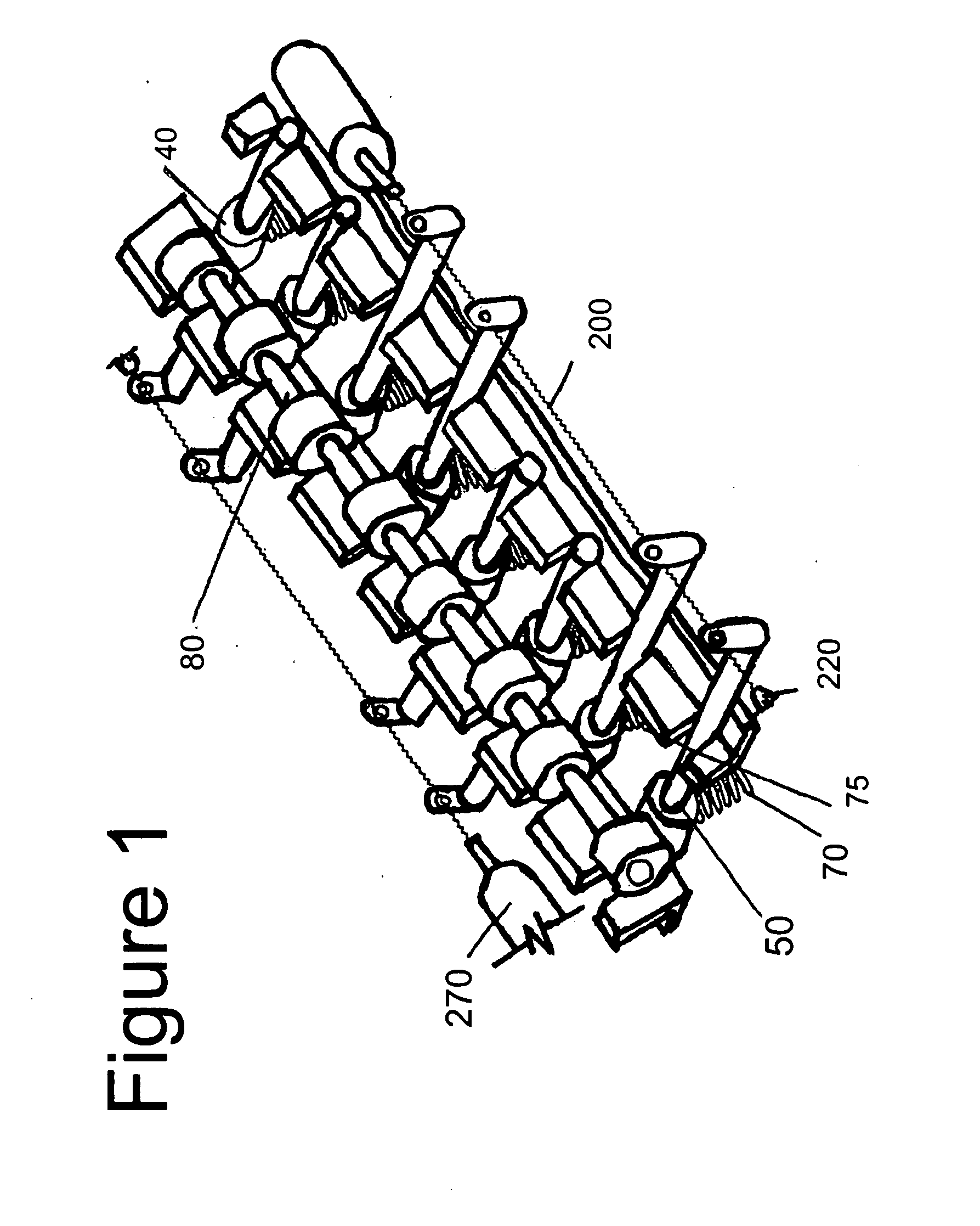
[0023]In FIG. 1, we see the elliptical apparatus (40) and function of the solenoids (220) attached to a typical four-cylinder engine. The size is structured so that it fits as a component of a transversal rotational axial bar (50) on top each piston (60).

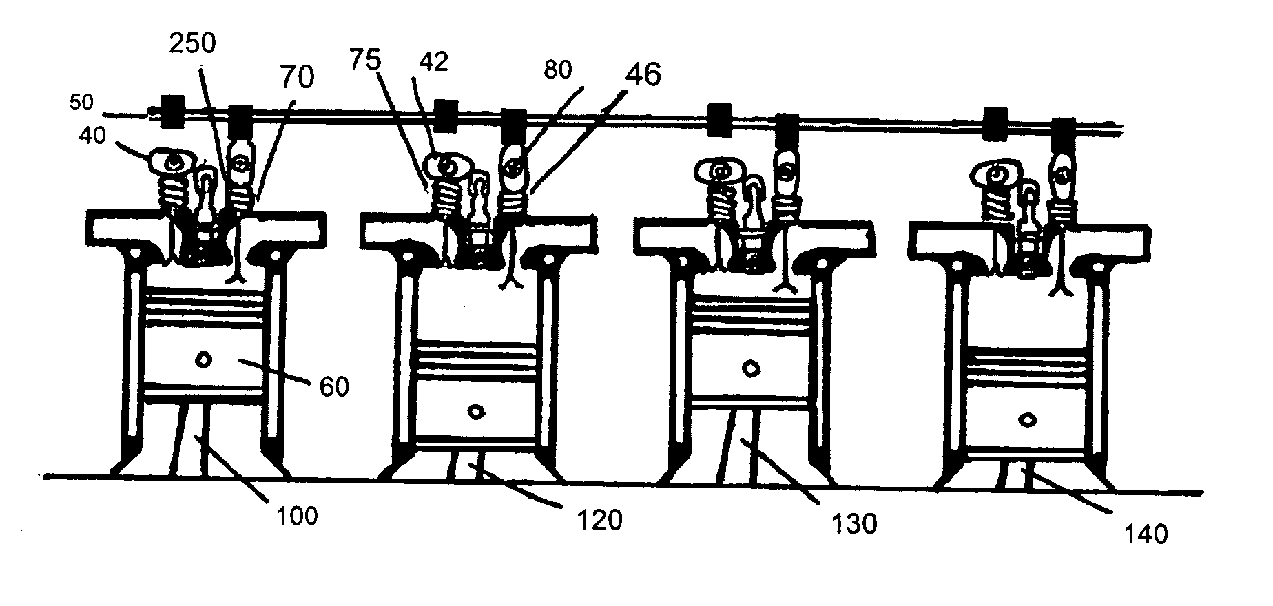
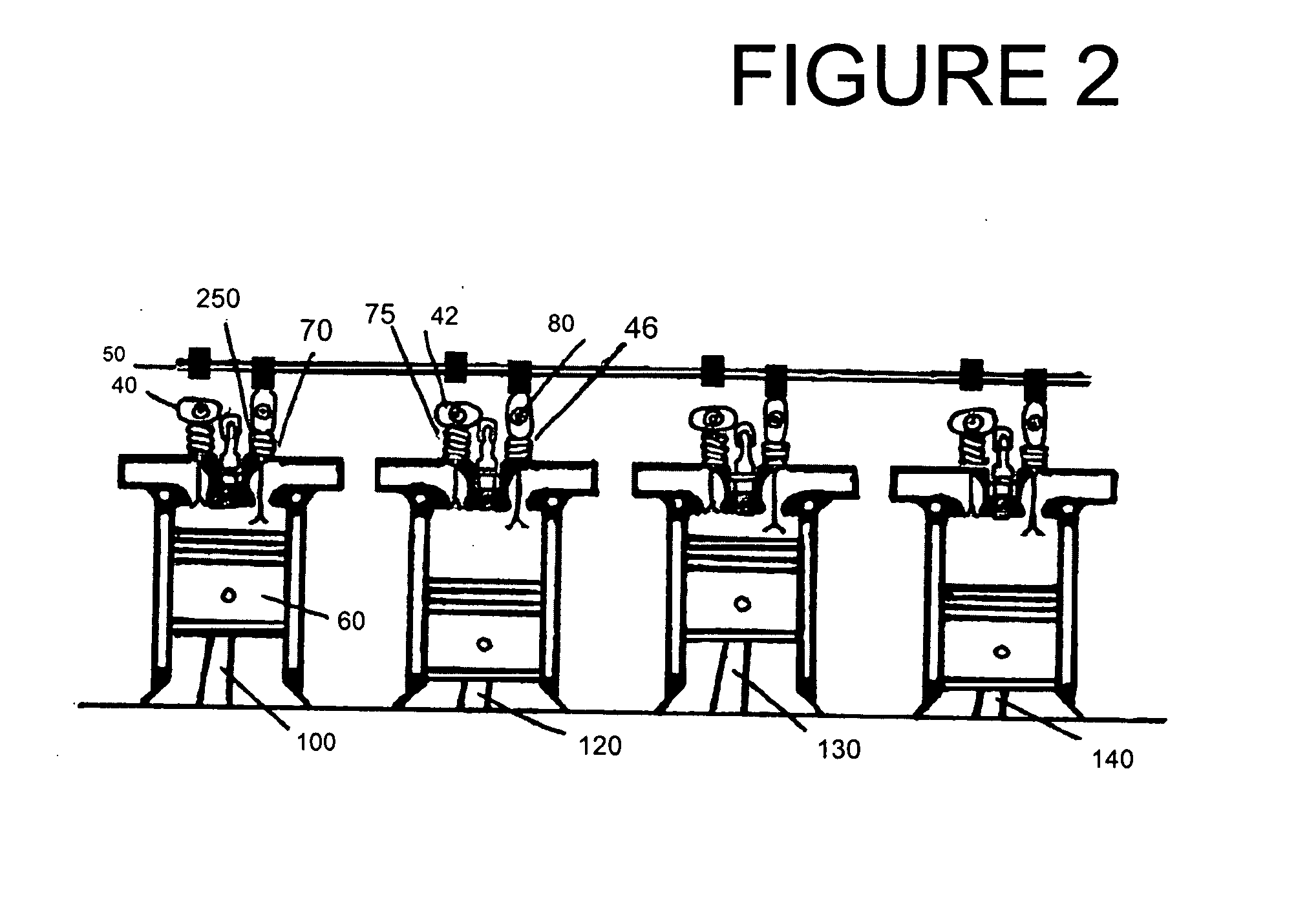
[0024]In FIG. 2, we see the various elements of the present invention as it would look under typical 4-cylinder engine conditions, including the placement of the elliptical apparatuses (40) in horizontal (42) and vertical (46) positions between the respective intake valves (70) and camshaft (80).

[0025]In FIG. 3, we see an additional embodiment of the present invention in relation to how it applies to fuel injection engines. Fuel injection engines contain some different physical elements and placements compared to carburetor engines. This includes the fuel injection valves (350), high-pressure injector (320), pressurized fuel valve (310), low-pressure injector (360), high-pressure pump (330) and the fuel tank (340)....


PUM


Abstract

An adaptable cylinder deactivating system for automobile engines that can easily and cost effectively be placed into virtually any existing or new engine to drastically reduce fuel consumption. This outcome is achieved by deactivating half of the cylinders while also eliminating compression at times when full power is not necessary. Elliptical apparatuses are placed within two semi-circular supports on each piston of the automobile engine between the camshaft and intake and exhaust valves using solenoids to determine exact positioning to ultimately reduce gas consumption for most types of engines, including diesel, gasoline and injection engines.

Description

[0001]This is a non-provisional application claiming priority to provisional patent application No. 60 / 894,080 filed on Mar. 9, 2007.FIELD OF THE INVENTION[0002]The present invention relates primarily to an elliptical apparatus and method that is placed within two semi-circular supports on each piston of the automobile engine between the camshaft and intake and exhaust valves using solenoids to determine exact positioning to reach the ultimate result of deactivating selected cylinders during engine operation to significantly reduce gas consumption for most types of engines, including diesel, gasoline and injection engines.BACKGROUND OF THE INVENTION[0003]We live in a highly mobile society. The vast majority of the population relies on automobiles to suit their ever-growing transportation needs. Whether it is large SUVs, pickup trucks, sports cars, sedans or virtually any other type of automobile on the market, people must pay ever fluctuating and uncertain fuel costs to keep moving....

Claims


Application Information

Patent Timeline
Patent Type & Authority Applications(United States)
IPC IPC(8): F01L1/06F02D17/02
CPCF01L1/181F01L13/0005F02D17/02F01L2820/032F01L13/0063
Inventor BILILIES, THEODORE C.
Owner BILILIES THEODORE C
Why Eureka
Try Eureka