
LED drive power supply and LED fluorescent lamp

An LED fluorescent lamp and LED driving technology, applied in the direction of electric light source, electric light source, electric lamp circuit layout, etc., can solve the problems of affecting the service life of power supply and LED, reducing product stability and reliability, adverse product quality improvement and automatic production, etc. , to achieve good environmental protection and recycling, easy assembly and maintenance, simple and convenient after-sales service

Inactive Publication Date: 2014-07-23
吴光
View PDF11 Cites 2 Cited by
  • Summary
  • Abstract
  • Description
  • Claims
  • Application Information

AI Technical Summary

Problems solved by technology

[0003] The existing LED fluorescent lamps are divided into two types: built-in power supply and external power supply. The LED fluorescent lamp with built-in power supply generates a lot of heat when the power supply circuit board is in use, and the LED substrate is also constantly heating when it is working. The two streams of heat converge on the Together, the internal temperature of the lamp tube will rise, which will not only affect the service life of the power supply and LED, but also reduce the stability and reliability of the product, resulting in damage to the power supply or LED.
The LED fluorescent lamps with external power supply are designed in different sizes due to different usage requirements. The lamp tubes and power supplies of various types are paired independently, but the lamp tubes and power supplies of different models cannot be paired and installed, which makes the difference between products Poor interchangeability, lack of compatibility considerations, resulting in high use and management costs, which is not conducive to product quality improvement and automated production

Method used


Image

  • LED drive power supply and LED fluorescent lamp
  • LED drive power supply and LED fluorescent lamp
  • LED drive power supply and LED fluorescent lamp

Examples


Embodiment Construction

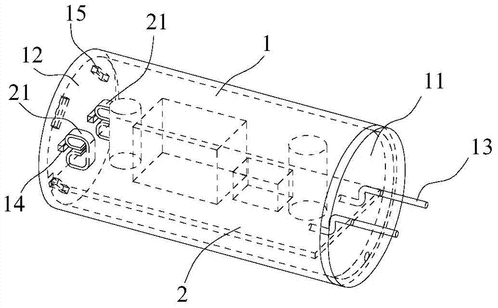
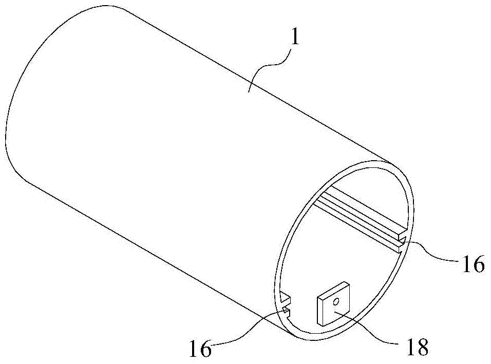
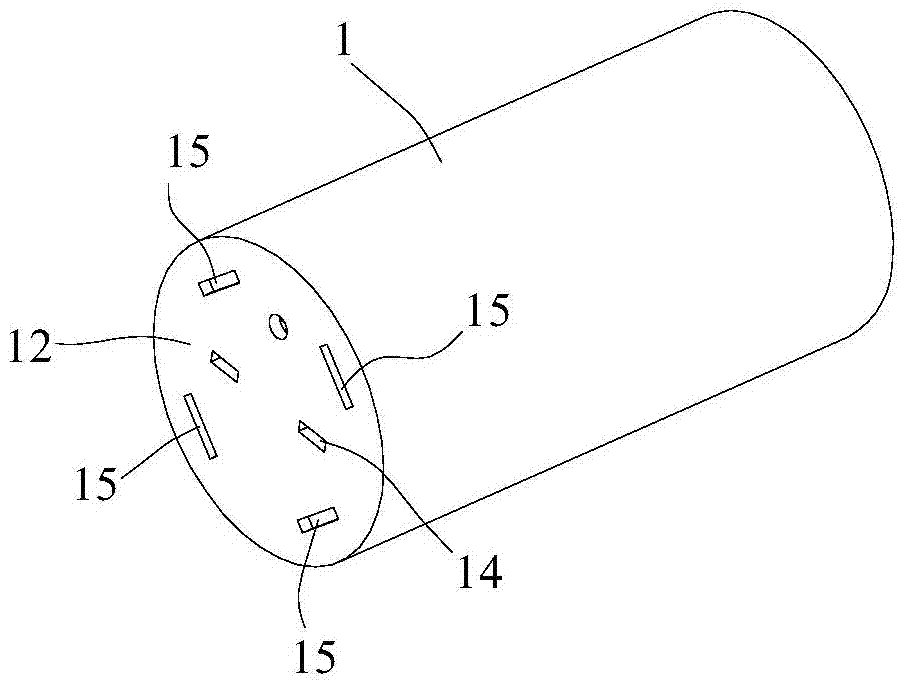
[0029] refer to Figure 1 to Figure 9 , the present invention provides an LED driving power supply, including a cylindrical casing 1, a rectifier circuit board 2 arranged in the casing 1, and a front end cover 11 and a rear end cover 12 that close the casing 1. The front end cover 11 leads out Two circular pins 13 connected to the rectifier circuit board 2, the rear end of the rectifier circuit board 2 is provided with two output contact card slots 21, and the rear end cover 12 is provided with two opposite output contact card slots The socket 14 of 21, the rear end cover 12 is provided with a plurality of connecting holes 15 around the socket 14, and the socket 14 and the connecting holes 15 are both square. Two opposite chute 16 are provided along the inner wall of the housing 1 . The rectifier circuit 2 board is embedded in the chute 16 and is clamped and fixed by the front end cover 11 and the rear end cover 12 .

[0030] The cover 1 and the rear end cover 12 are integral...


PUM


Abstract

The invention discloses an LED drive power supply and an LED fluorescent lamp, and belongs to the field of illumination lamps. The LED drive power supply achieves alternating and direct current conversion from a round pin to an untouched output contact clamping groove through a rectifier circuit board; the LED fluorescent lamp is connected with an output contact clamping groove in a drive power supply socket through a pin led out from a clamping plug to achieve direct-current circuit connection of an LED lamp stripe. The LED drive power supply and a lamp tube of the LED fluorescent lamp are manufactured and assembled in a split mode, the connection process of structure assembly is adopted and replaces a traditional bonding line connection production technology, product assembly and maintenance are easy to achieve, quality is improved, material cost is lowered, management cost is lowered, and automated production is facilitated. When lamp tubes of LED fluorescent lamps of different types are replaced, people only need to replace the clamping plug, good interchangeability among products is achieved, the situation that more products are formed through combination of the smallest number of parts is achieved, product after-sale service is easy and convenient to achieve, and meanwhile environmental protection and recycling performance are good.

Description

technical field [0001] The invention is used in the field of lighting lamps, and particularly relates to an LED driving power supply and an LED fluorescent lamp. Background technique [0002] In recent years, with the continuous improvement of light-emitting diode (Light-Emitting Diode, LED) technology, the performance of LED lamps for lighting has been greatly improved. Significant advantages, no ultraviolet radiation and environmental pollution, and high safety in use have been widely recognized and have become the mainstream of energy-saving lamps in the future. [0003] The existing LED fluorescent lamps are divided into two types: built-in power supply and external power supply. The LED fluorescent lamp with built-in power supply generates high heat due to the power circuit board in use, and the LED substrate is also constantly heating during operation. At the same time, the internal temperature of the lamp is increased, which not only affects the service life of the p...

Claims


Application Information

Patent Timeline
Patent Type & Authority Applications(China)
IPC IPC(8): H05B37/02F21S2/00F21V19/00F21Y101/02
Inventor 吴光吴蓉吴曦
Owner 吴光
Learn More