Conductive-pattern formation method and composition for forming conductive pattern via light exposure or microwave heating

A conductive pattern, microwave heating technology, applied in the direction of conductive pattern formation, conductive materials dispersed in non-conductive inorganic materials, conductive coatings, etc., can solve the problem of copper oxide particle residue, conductive pattern conductivity can not be fully improved, conductive pattern pores High conductivity and other problems, to achieve the effect of improving conductivity

Active Publication Date: 2014-07-23
RESONAC CORPORATION
View PDF7 Cites 2 Cited by
  • Summary
  • Abstract
  • Description
  • Claims
  • Application Information

AI Technical Summary

Problems solved by technology

[0006] The method of using light energy or microwave heating can heat only the ink part, which is a very good method, but in the case of using metal particles themselves, there is a problem that the conductivity of the obtained conductive pattern cannot be sufficiently improved. In the case of copper oxide, there is a problem that the porosity of the obtained conductive pattern is large, and some copper oxide particles remain without being reduced.
[0007] In addition, their sintering requires the use of metal or metal oxide particles with a diameter of at least 1 μm or less, and there is a problem that the preparation of these nanoparticles is very costly

Method used


Image

  • Conductive-pattern formation method and composition for forming conductive pattern via light exposure or microwave heating
  • Conductive-pattern formation method and composition for forming conductive pattern via light exposure or microwave heating
  • Conductive-pattern formation method and composition for forming conductive pattern via light exposure or microwave heating

Examples


Embodiment 1

[0059] In a mixed aqueous solution (weight ratio ethylene glycol: glycerol: water = 70:15:15) of ethylene glycol and glycerin (a reagent manufactured by Kanto Chemical Co., Ltd.) as a reducing agent, dissolve the polyethylene group as a binder Pyrrolidone (manufactured by Nippon Shokubai Co., Ltd.) prepared a 40% by mass binder solution. 1.5 g of this solution was mixed with 0.5 g of the above-mentioned mixed aqueous solution, and 5.4 g of copper powder 1050Y (spherical shape, D50=716 nm) manufactured by Mitsui Metal Mining Co., Ltd. and N300 (flat shape (flat shape ( Thickness: 30nm), D50 = 470nm) 0.6g (copper particles: silver particles = 90:10), using the rotation and revolution vacuum mixer Awatori Rentaro ARV-310 (manufactured by Shinki Co., Ltd.) to mix well and make for printing paste (conductive pattern forming composition).

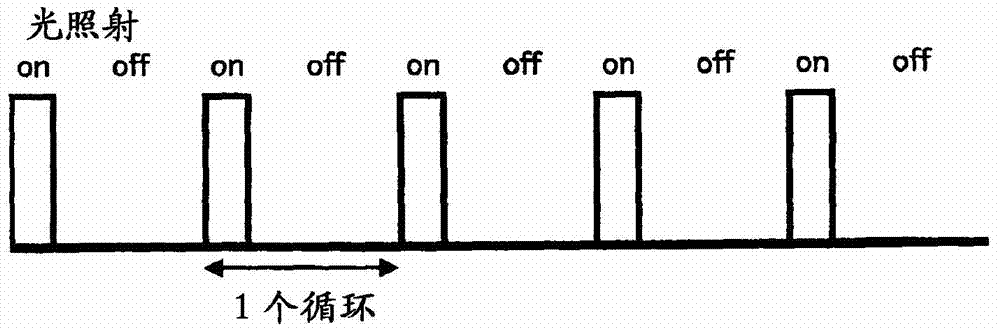
[0060] The obtained paste was screen-printed to print a 2 cm x 2 cm square pattern on a polyimide film (Capton 100V, manufactured by Toray Dupo...

Embodiment 2

[0062] Using 5.4 g of copper powder 1100Y (spherical shape, D50=1110 nm) manufactured by Mitsui Metal Mining Co., Ltd. and 0.6 g of N300 (flat shape (thickness: 30 nm), D50=470 nm) manufactured by Tokusen Industry Co., Ltd. as silver particles, and Example 1 A paste for printing was prepared in the same manner. The obtained paste was subjected to pattern printing and light irradiation in the same manner as in Example 1. The thickness of the formed conductive pattern was 23 μm.

Embodiment 3

[0064] Using 5.4 g of copper powder 1400Y (spherical, D50 = 5700 nm) manufactured by Mitsui Metal Mining Co., Ltd. and 0.6 g of N300 (flat shape (thickness: 30 nm), D50 = 470 nm) manufactured by Tokusen Industry Co., Ltd. as silver particles, and Example 1 A paste for printing was prepared in the same manner. The obtained paste was subjected to pattern printing and light irradiation in the same manner as in Example 1. The thickness of the formed conductive pattern was 26 μm.


PUM

PropertyMeasurementUnit
thicknessaaaaaaaaaa
particle sizeaaaaaaaaaa
wavelengthaaaaaaaaaa

Abstract

[Problem] To provide the following: a conductive-pattern formation method that can improve the conductivity of the conductive pattern; and a composition for forming a conductive pattern via light exposure or microwave heating. [Solution] A conductive-pattern-forming composition containing the following is prepared: copper particles with a copper-oxide thin film formed on the entire surface or part of the surface of each particle; plate-shaped silver particles with thicknesses of 10 to 200 nm; and a binder resin. Said conductive-pattern-forming composition is used to form an arbitrarily-shaped printed pattern on a substrate, and said printed pattern is exposed to light or microwave-heated to produce a sintered copper / silver body, thereby forming a conductive film.

Description

technical field [0001] The present invention relates to an improvement of a conductive pattern forming method and a conductive pattern forming composition for forming a conductive pattern by light irradiation or microwave heating. Background technique [0002] As a technique for producing fine wiring patterns, the method of forming wiring patterns by combining copper foil and photoresist by photolithography has been generally used so far. The burden is heavy, and improvement in the environment is desired. In addition, a method of patterning a metal thin film produced by thermal vapor deposition or sputtering by photolithography is also known. However, the heating vapor deposition method and the sputtering method are not only indispensable in a vacuum environment, but are also very expensive, and it is difficult to reduce the manufacturing cost when applied to a wiring pattern. [0003] Then, a technique of forming wiring by printing using an ink containing metal and / or met...

Claims


Application Information

Patent Timeline
Patent Type & Authority Applications(China)
IPC IPC(8): H05K3/12C09D5/24C09D7/12C09D171/02C09D201/00H01B1/00H01B1/22H01B13/00C09D7/62
CPCC09D5/24H01B1/22H05K1/095H05K2201/0245H05K2201/0257H05K2201/0272C08K2003/0806C08K2003/085C08K2201/002C08K2201/014C09D7/62C09D7/70H05K3/1283H05K2203/10H05K2203/102
Inventor 内田博
Owner RESONAC CORPORATION
Why Eureka
Try Eureka