Supercharge Your Innovation With Domain-Expert AI Agents!

A grinding roller removal mechanism of a pulverizer

A technology of milling machine and grinding roller, which is applied in the direction of grain processing, etc., and can solve the problems of heavy disassembly workload, affecting production, and long time

Inactive Publication Date: 2016-05-04
河南省新乡县四达有限公司 +1
View PDF8 Cites 0 Cited by
  • Summary
  • Abstract
  • Description
  • Claims
  • Application Information

AI Technical Summary

Problems solved by technology

The current method is to remove the grinding roller and then move it out for replacement. The disassembly workload is heavy and the time is long, which affects production

Method used


Image

  • A grinding roller removal mechanism of a pulverizer

Examples


Embodiment Construction

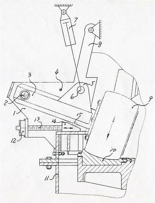
[0008] The present invention has the following embodiments, each grinding roller 9 has a cantilever shaft 3, the outer end of the cantilever shaft is hinged with the pin shaft 2 fixed on the grinding roller bracket 1, and a limit position is fixed on the grinding roller bracket above the cantilever shaft The shaft 4 is opposite to the above-mentioned cantilever shaft, and the upper side of the above-mentioned cantilever shaft is provided with an outwardly protruding ear plate 5, and the piston rod of the hydraulic cylinder 7 fixed on the frame 11 is hinged to the pin shaft 6 on the above-mentioned ear plate. The pendulum plate 8 on the support top is hinged with the pin on the frame.

[0009] The slide block 14 is slidably supported on the guide rail of the frame, the upper end surface of the slide block has an inclined surface, the roller bar 15 is supported between the above-mentioned cantilever shaft and the inclined surface of the slide block, and one end of the screw rod 1...


PUM


Abstract

The invention discloses a grinding roller removal mechanism for a pulverizing mill. The grinding roller removal mechanism for the pulverizing mill comprises grinding rollers and grinding roller shafts, wherein the grinding roller shafts are cantilever shafts; the outer end of each shaft is hinged to a grinding roller bracket; a piston rod of an oil cylinder which is arranged on a rack is hinged to each cantilever shaft; a protruded limiting shaft is arranged on each bracket and is opposite to each cantilever shaft beneath the limiting shaft; a pin shaft is arranged at the position, on the right side of the axis of a hydraulic cylinder, on the rack; a swinging plate at the upper part of each grinding roller bracket is hinged to the corresponding pin shaft at the upper part of the rack. The grinding roller removal mechanism for the pulverizing mill has the remarkable advantages that the grinding rollers can be quickly and conveniently removed; the pressure of the grinding rollers can be conveniently adjusted; the pulverizing mill is not damaged.

Description

technical field [0001] The invention relates to a grinding equipment, in particular to a grinding roll removal mechanism of a grinding machine. Background technique [0002] The existing fly ash processing equipment mainly includes vertical pulverizers and tube mills. The vertical pulverizers are widely used due to their high efficiency. The grinding roller needs to be removed from the mill chamber of the pulverizer for replacement. The current method is to remove the grinding roller and then remove it for replacement. The workload of disassembly is large and the time is long, which affects production. Contents of the invention [0003] The object of the present invention is to provide a grinding roller removing mechanism of a pulverizer which is fast and convenient for overhauling the grinding roller. [0004] Another object of the present invention is to provide a grinding roll removal mechanism of a pulverizer that can adjust the pressure on the grinding roll without ...

Claims


Application Information

Patent Timeline
Patent Type & Authority Patents(China)
IPC IPC(8): B02C15/00
Inventor 周雁杜朝辉崔平倪明东范国录韩二宝张宗磊李良国马胜钢雷玺吕凯丽张坤刘春玲王明霞
Owner 河南省新乡县四达有限公司
Features
  • R&D
  • Intellectual Property
  • Life Sciences
  • Materials
  • Tech Scout
  • Unparalleled Data Quality
  • Higher Quality Content
  • 60% Fewer Hallucinations
Learn More