A punching die for rear suspension mounting bracket
What is AI technical title?
AI technical title is built by PatSnap AI team. It summarizes the technical point description of the patent document.
A mounting bracket and rear suspension technology, applied in the field of punching dies, can solve the problems of difficult to guarantee the positioning size, difficult installation and positioning of the rear suspension mounting bracket, inapplicable rear suspension mounting bracket, etc., so as to ensure the performance and avoid The effect of blocking and reducing the repair rate
Active Publication Date: 2016-06-08
芜湖中瑞汽车零部件有限公司
View PDF7 Cites 0 Cited by
Summary
Abstract
Description
Claims
Application Information
AI Technical Summary
This helps you quickly interpret patents by identifying the three key elements:
Problems solved by technology
Method used
Benefits of technology
Problems solved by technology
The mold has a simple and reasonable structural design, fast opening and closing speed of the stamping die, high processing efficiency, compact structural design, small size, and is convenient for mold installation and management, but the mold is not suitable for rear suspension mounting brackets. The reason is that the structural characteristics of the rear suspension support and the rear suspension mounting bracket are different, and the parts that need to be punched are different, and the positioning of the rear suspension support is relatively simple. This mold can meet the positioning requirements, and the installation of the rear suspension mounting bracket Positioning is difficult, and the positioning size is difficult to guarantee
Method used
Image
Click on the blue label to locate the original text in one second.
Reading with bidirectional positioning of images and text.
Examples
Embodiment Construction
[0017] In order to make the technical means, creative features, goals and effects achieved by the present invention easy to understand, the present invention will be further elaborated below.
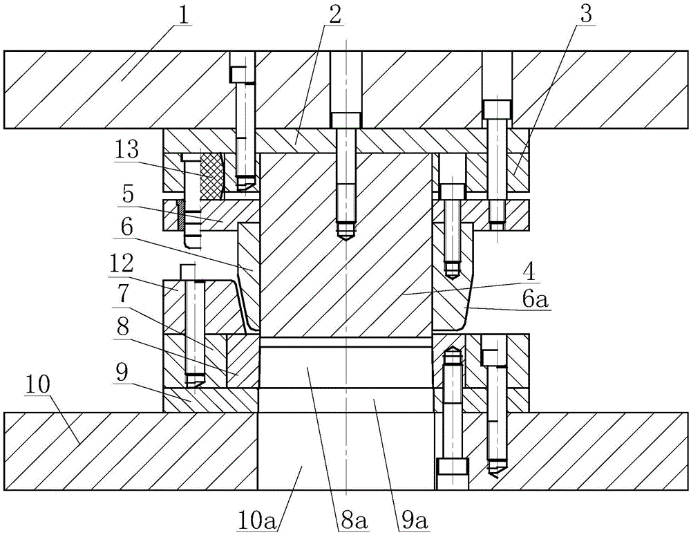
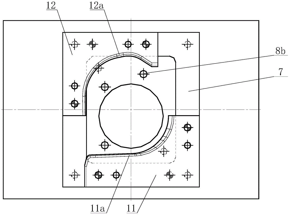
[0018] Such as Figure 1 to Figure 3 As shown, a punching die for a rear suspension mounting bracket includes an upper die and a lower die, and the upper die includes an upper template 1, an upper backing plate 2, an upper fixing plate 3, a punch 4, a binder plate 5 and Convex mold 6, described lower mold comprises die insert 7, die 8, lower backing plate 9, lower template 10, right L-shaped positioning block 11 and left L-shaped positioning block 12, and described lower backing plate 9 is fixedly connected Above the lower template 10, the die insert 7 and the die 8 are fixed above the lower backing plate 9, the upper backing plate 2 is fixed under the upper template 1, and the upper fixing plate 3 is fixed on the upper backing plate 2, the left side of the upper fixing plate 3 is inla...
PUM
Abstract
The invention relates to a punching die of a rear suspension installation bracket. The punching die comprises an upper die and a lower die, wherein the upper die comprises an upper die plate, an upper padding plate, an upper fixing plate, a punching head, a pressing plate and a male die, the lower die comprises a female die insert, a female die, a lower padding plate, a lower die plate, a right L-shaped locating block and a left L-shaped locating block, an elastic element is embedded in the left side of the upper fixing plate, the lower end of the elastic element is connected with the pressing plate, the punching head is clamped in the middle part of the upper fixing plate and the pressing plate, the upper end of the male die is fixedly connected with the middle lower part of the pressing plate, the lower end of the punching head penetrates through the male die, the female die is installed in the female die insert, the left L-shaped locating block is fixed at the left rear part of the upper part of the male die and the male die insert, and the right L-shaped locating block is fixed at the right front part of the upper part of the male die and the male die insert. The punching die of the rear suspension installation bracket has the advantages of reasonable structure design, convenience in control, high punching efficiency and the like, and the locating size of a to-be-punched part is guaranteed, so that the repair rate is reduced, the part is automatically separated, and convenience is provided for the use of an operator.
Description
technical field [0001] The invention relates to the technical field of auto parts processing, in particular to a punching die for a rear suspension mounting bracket. Background technique [0002] The structural features of the rear suspension mounting bracket commonly used in automobiles include the mounting surface and the side block. The middle part of the mounting surface needs to be punched so as to be used for positioning and connection with other parts on the automobile. When using the existing punching die to punch it, because the punching process is after the flanging of the side stop, and the structural characteristics of the side stop are not convenient for lateral positioning, it is easy to produce positioning errors, resulting in punching The dimensional accuracy of the hole is poor, which affects the installation and use of the rear suspension mounting bracket. The position of the hole needs to be corrected repeatedly to meet the use requirements. The repair rat...
Claims
Application Information
Patent Timeline
Application Date:The date an application was filed.
Publication Date:The date a patent or application was officially published.
First Publication Date:The earliest publication date of a patent with the same application number.
Issue Date:Publication date of the patent grant document.
PCT Entry Date:The Entry date of PCT National Phase.
Estimated Expiry Date:The statutory expiry date of a patent right according to the Patent Law, and it is the longest term of protection that the patent right can achieve without the termination of the patent right due to other reasons(Term extension factor has been taken into account ).
Invalid Date:Actual expiry date is based on effective date or publication date of legal transaction data of invalid patent.

