
Method and device for sleeving central air-conditioning capillary tube with heat shrink tube

A central air-conditioning and capillary technology, which is applied in metal processing equipment, metal processing, manufacturing tools, etc., can solve the problems of low work efficiency, high labor intensity, poor consistency of casing position, etc., to achieve simple action and reduce labor intensity. , good effect of casing position consistency

Inactive Publication Date: 2014-07-30
ANHUI UNIVERSITY
View PDF5 Cites 11 Cited by
  • Summary
  • Abstract
  • Description
  • Claims
  • Application Information

AI Technical Summary

Problems solved by technology

High labor intensity, low work efficiency, poor casing position consistency

Method used


Image

  • Method and device for sleeving central air-conditioning capillary tube with heat shrink tube
  • Method and device for sleeving central air-conditioning capillary tube with heat shrink tube
  • Method and device for sleeving central air-conditioning capillary tube with heat shrink tube

Examples


Embodiment 1

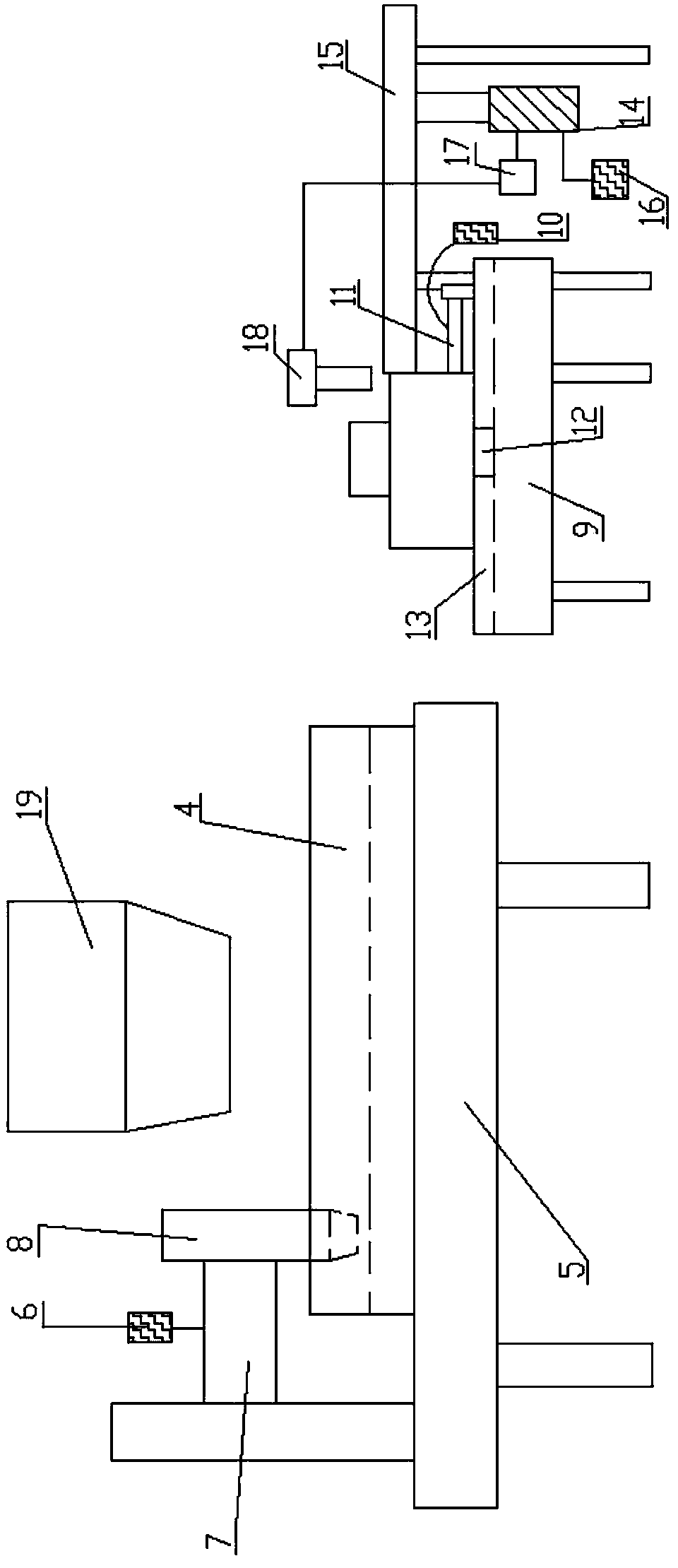
[0031] combine figure 1 , figure 2 , image 3 , a method for covering heat-shrinkable tubes on central air-conditioning capillary tubes, comprising the following steps:

[0032] (1) Clamp the outer surface of one end of the heat-shrinkable tube 2 with the clamp 1; the heat-shrinkable tube 2 can be firmly restrained. During the process of inserting the capillary 3 into the heat-shrinkable tube 2, the friction between the capillary 3 and the heat-shrinkable tube 2 It will not cause the heat-shrinkable tube 2 to move, which solves the problem of automatically placing the capillary 3 on the designated position of the soft heat-shrinkable tube;

[0033] (2) Place the capillary 3 on the V-shaped track 4 so that the center of the capillary 3 is aligned with the center of the heat-shrinkable tube 2;

[0034] (3) Use the first driving device to drive the capillary 3 to move toward the clamp 1 , and insert the capillary 3 into the heat shrinkable tube 2 .

[0035] A device for putt...

Embodiment 2

[0043] combine figure 1 , figure 2 , Figure 4 , a method for covering heat-shrinkable tubes on central air-conditioning capillary tubes, comprising the following steps:

[0044] (1) Clamp the outer surface of one end of the heat-shrinkable tube 2 with the clamp 1; the heat-shrinkable tube 2 can be firmly restrained. During the process of inserting the capillary 3 into the heat-shrinkable tube 2, the friction between the capillary 3 and the heat-shrinkable tube 2 It will not cause the heat-shrinkable tube 2 to move, which solves the problem of automatically placing the capillary 3 on the designated position of the soft heat-shrinkable tube;

[0045] (2) Place the capillary 3 on the V-shaped track 4 so that the center of the capillary 3 is aligned with the center of the heat-shrinkable tube 2;

[0046] (3) Use the first driving device to drive the capillary 3 to move toward the clamp 1 , and insert the capillary 3 into the heat shrinkable tube 2 .

[0047] A device for put...


PUM


Abstract

The invention discloses a method and device for sleeving a central air-conditioning capillary tube with a heat shrink tube. The method comprises the following steps: (1) clamping the outer surface at one end of the heat shrink tube by using a clamp; (2) putting the capillary tube on the surface of a V-shaped track, and aligning the center of the capillary tube to the center of the heat shrink tube; (3) driving the capillary tube to move to the clamp through a first driving device, and inserting the capillary tube into the heat shrink tube. The technical scheme is reliable in mechanical structure, simple in action and capable of greatly improving the production efficiency and reducing the labor strength.

Description

technical field [0001] The invention relates to the technical field of central air-conditioning, and more specifically relates to a method and a device for covering a heat-shrinkable tube on a central air-conditioning capillary. Background technique [0002] Refrigeration technology for air-conditioning belongs to the scope of general refrigeration, mainly using liquid vaporization refrigeration method. The use of liquid gasification process requires absorption of specific latent heat, and the boiling point of the liquid is different with the pressure of the liquid. The lower the pressure, the lower the boiling point. [0003] The central air conditioning system consists of a cold and heat source system and an air conditioning system. The refrigeration system provides the required cooling capacity for the air conditioning system to offset the cooling load of the indoor environment; the heating system provides the air conditioning system with heat to offset the heat load of ...

Claims


Application Information

Patent Timeline
Patent Type & Authority Applications(China)
IPC IPC(8): B23P19/04
CPCB23P19/04
Inventor 张涛
Owner ANHUI UNIVERSITY
Learn More