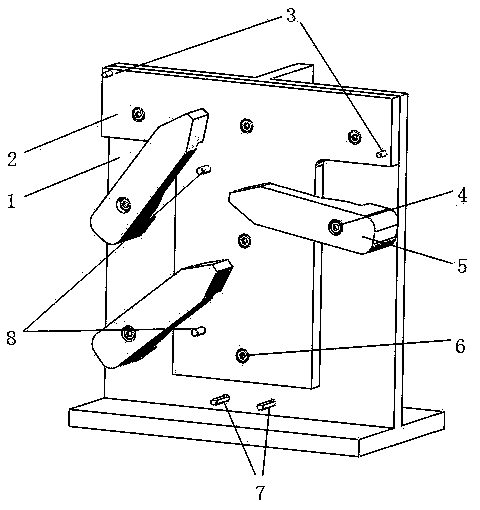
[0013] The embodiments of the present invention are described in detail below. Examples of the embodiments are shown in the accompanying drawings, in which the same or similar reference numerals indicate the same or similar elements or elements with the same or similar functions. The embodiments described below with reference to the drawings are exemplary, and are only used to explain the present invention, but should not be construed as limiting the present invention.
[0014] In the description of the present invention, unless otherwise specified and limited, it should be noted that the terms "installed", "connected", and "connected" should be understood in a broad sense. For example, they can be mechanically connected or electrically connected, or two The internal communication of the components can be directly connected or indirectly connected through an intermediate medium. For those of ordinary skill in the art, the specific meaning of the above-mentioned terms can be understood according to specific circumstances.
[0015] Refer below figure 1 A special fixture for CNC machining grooves according to an embodiment of the present invention is described. A special fixture for CNC machining grooves, comprising a bottom frame 1 and a fixture main board 2. The bottom frame 1 is a "convex"-shaped bottom frame, and one side of the convex part in the middle of the bottom frame 1 extends outward to form a support plate. There is a fixture main board 2 on the side of the other side of the starting part. The fixture main board 2 is fixed on the side of the raised part of the base frame 1 by 5 M12 fixing screws 6. The fixture main board 2 is a "T"-shaped main board, and the fixture also includes a fixing unit And positioning unit, there are three fixing units, the fixing unit specifically includes pressing block 5 and M10 fixing screw 4. The pressing block 5 is fixed on the chassis 1 by M10 fixing screw 4, and two fixing units are set on the "T"-shaped main board 2 On the bottom frame 1 on one side of the vertical part, and the two fixing units are located on the same vertical line, the other fixing unit is set on the bottom frame 1 on the other side of the vertical part, and this fixing unit is fixed to the higher one on the other side. The units are on the same horizontal line; there are three positioning units, the positioning unit specifically includes two positioning pins, two D8 shaped positioning pins 7 are set on the bottom frame 1 below the vertical part of the "T"-shaped main board 2, and two D8 The special-shaped positioning pins 7 are located at the same height and in the middle position of the chassis 1. Two D8 positioning pins 8 are provided on the side of the vertical part of the "T"-shaped main board 2, and the two D8 positioning pins 8 are located on the same vertical line. The D6 positioning pins 3 are respectively arranged on two opposite corners of the horizontal part of the "T"-shaped main board 2.
[0016] The CNC machining groove clamping method of the present invention includes the following steps:
[0017] 1) Groove processing, place the workpiece to be processed on the vertical part of the fixture main board 2, the lower end of the workpiece is against the two D8 shaped positioning pins 7, the side of the workpiece is against the two D8 positioning pins 8, and then the three Press the block 5 on the workpiece, tighten the M10 fixing screw 4 to complete the clamping of the workpiece, and then the machine tool completes the groove processing of the workpiece;
[0018] 2) Machining in the front groove, after completing step 1), take out the workpiece, place the workpiece on the horizontal part of the fixture main board 2, and align the positioning hole of the workpiece with the two D6 positioning pins 3 of the horizontal part of the fixture main board 2 to complete the positioning , Press the two pressing blocks 5 close to the workpiece on the workpiece, tighten the M10 fixing screw 4 to complete the clamping of the workpiece, and then the machine tool completes the machining of the front groove of the workpiece;
[0019] 3) Machining in the reverse groove, after completing step 2), take out the workpiece, turn the workpiece over and place it on the horizontal part of the fixture main board 2, and place the positioning hole of the workpiece on the two D6 positioning pins 3 of the horizontal part of the fixture main board 2. The positioning is completed, the two pressing blocks 5 close to the workpiece are pressed on the workpiece, the M10 fixing screw 4 is tightened to complete the clamping of the workpiece, and then the machine tool completes the machining of the front groove of the workpiece.
[0020] In order to solve the problem of relatively time-consuming processing and unstable processing dimensions caused by the need to exchange three fixtures to complete the processing of the earlier fixtures. The present invention adjusts the overall design and positioning mode of the fixture, combines the positioning of the hole and the shape on a fixture, and completes three processes on the same fixture. The positioning method of the hole adopts two diagonal positioning methods. When the groove is processed, the workpiece to be processed is placed on the vertical part of the fixture main board, the lower end of the workpiece is against the two D8 special-shaped positioning pins, the side of the workpiece is against the two D8 positioning pins, and then the three pressing blocks Press on the workpiece and tighten the M10 fixing screws to complete the clamping of the workpiece. When processing the groove, place the workpiece on the horizontal part of the fixture main board. The positioning hole of the workpiece is aligned with the two D6 positioning pins on the horizontal part of the fixture main board. Complete the positioning, press the two pressure blocks close to the workpiece on the workpiece, tighten the M10 fixing screw, and complete the clamping of the workpiece, so that the flatness and stability of the workpiece are well controlled during processing, and the groove is solved. Difficult to process, improving the processing accuracy and production efficiency.
[0021] In the description of this specification, the description with reference to the terms "one embodiment", "example", or "some examples" etc. means that a specific feature, structure, material or characteristic described in combination with the embodiment or example is included in the present invention. In at least one embodiment or example. In this specification, the schematic representation of the above-mentioned terms does not necessarily refer to the same embodiment or example. Moreover, the described specific features, structures, materials or characteristics may be combined in any one or more embodiments or examples in a suitable manner.
[0022] Although the embodiments of the present invention have been shown and described, those of ordinary skill in the art can understand that various changes, modifications, substitutions and modifications can be made to these embodiments without departing from the principle and purpose of the present invention. The scope of the present invention is defined by the claims and their equivalents.