Coiling device for flexible circuit plate

A flexible circuit and plate roll technology, which is applied in the directions of printed circuit, printed circuit, printed circuit manufacturing, etc., can solve the problems such as the unsmooth rotation of the turntable 103, the unbalanced force of the turntable 103, and the unsteady and firm structure. The effect of disengagement, smooth rotation and force balance

Active Publication Date: 2014-07-30
DONGGUAN DADIAN ELECTRONICS +1
View PDF10 Cites 8 Cited by
  • Summary
  • Abstract
  • Description
  • Claims
  • Application Information

AI Technical Summary

Problems solved by technology

[0005] The shortcomings of the early flexible circuit board unwinding device are: 1. The upper and lower housing structure composed of the upper housing 101 and the lower housing 102 is only supported by 4 plastic columns, that is, it has only 4 connection points, and it is easy to go up and down. 2. There is only one scroll spring 104, and the scroll spring 104 is located on the upper part of the turntable 103. When the flexible circuit board stretches at 108, the force exerted by the scroll spring 104 when it diverges or tightens The reaction force is concentrated on the upper part of the turntable 103, causing the force on the turntable 103 to be unbalanced, causing the turntable 103 to rotate unsmoothly or even damaged

Method used


Image

  • Coiling device for flexible circuit plate
  • Coiling device for flexible circuit plate
  • Coiling device for flexible circuit plate

Examples


Embodiment 1

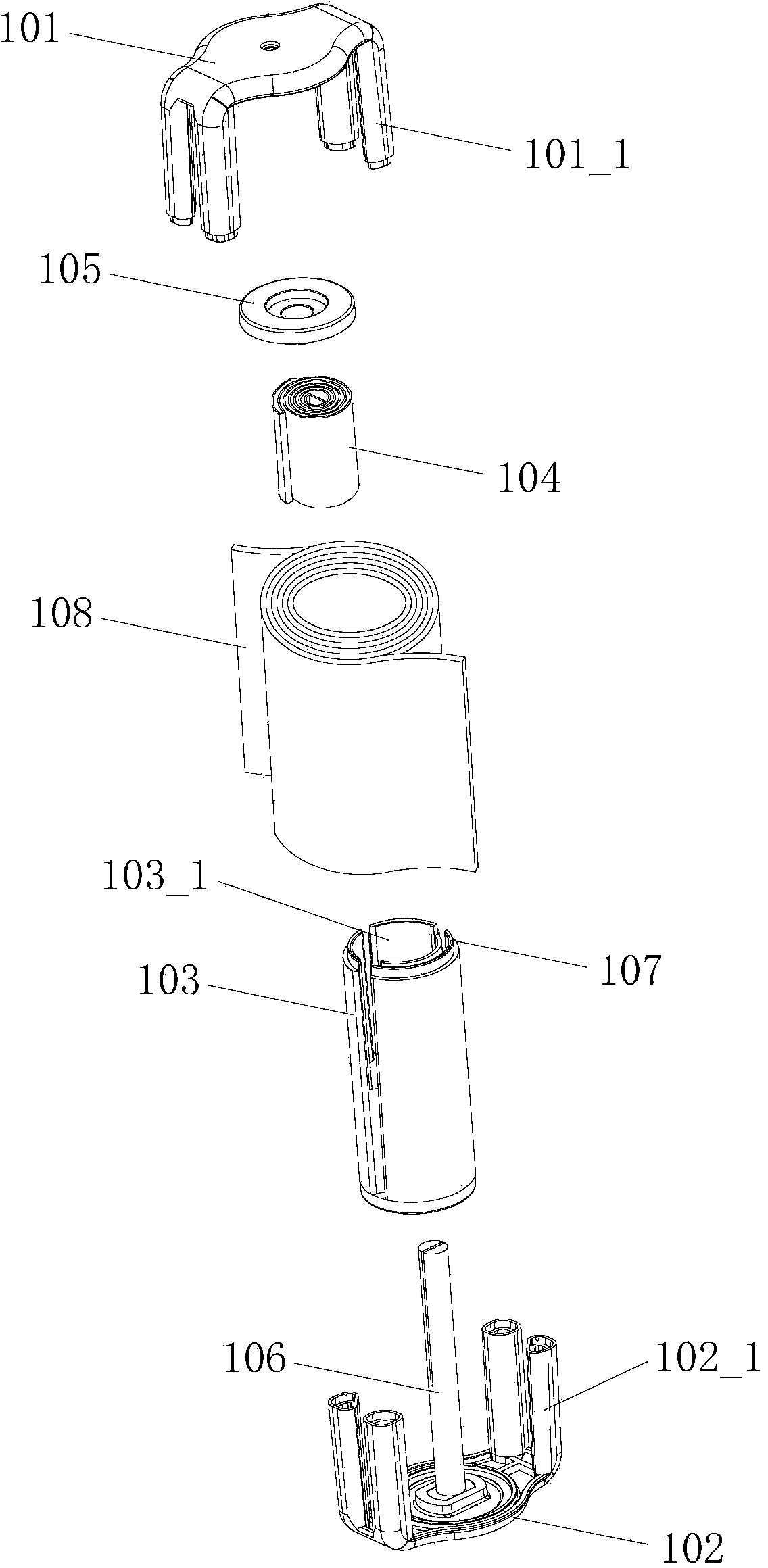
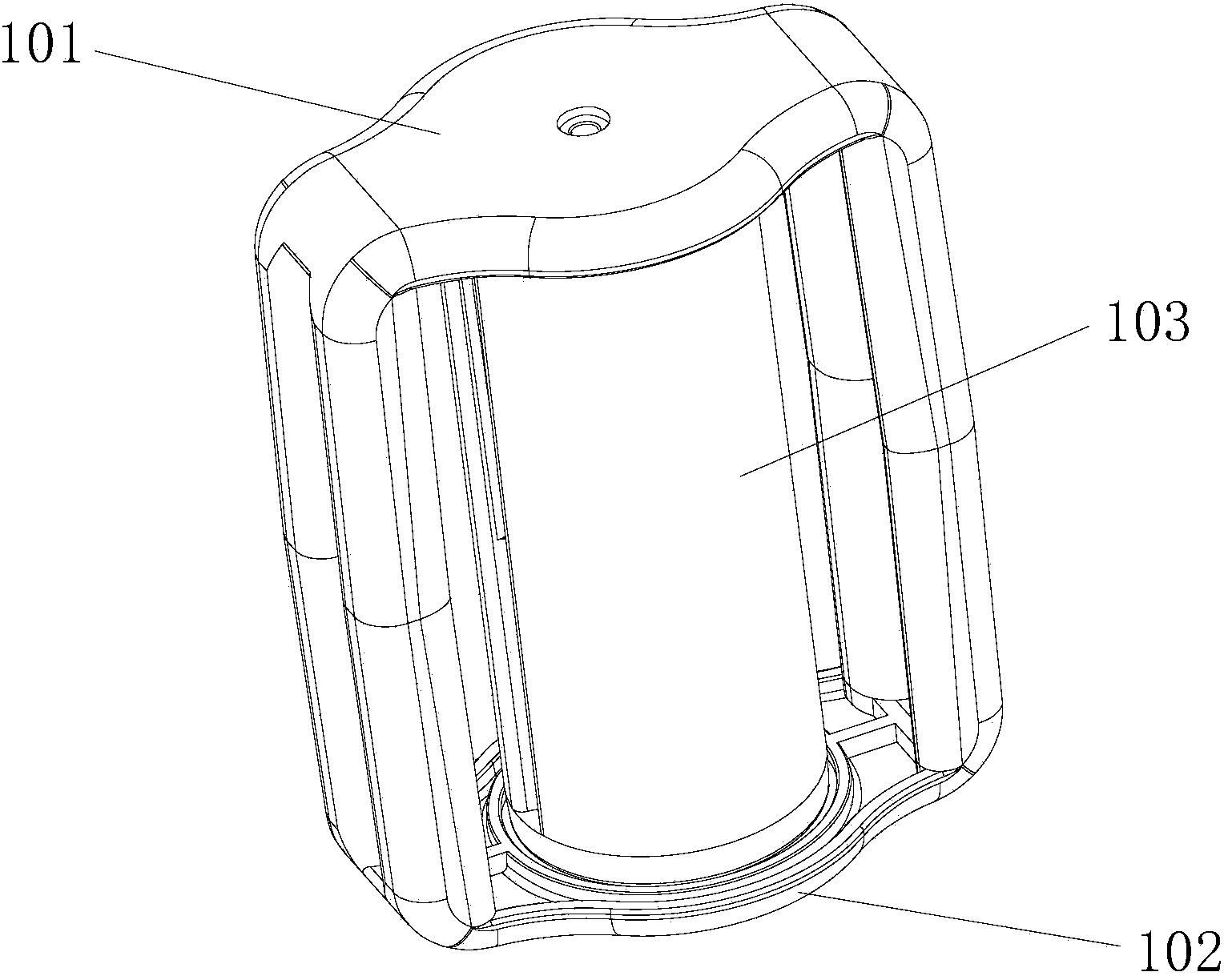
[0033] Please refer to Figure 3-14, the flexible circuit board unwinding device of the present invention includes a left casing 1 , a right casing 2 , a turntable 3 , an upper scroll spring 41 , and a lower scroll spring 42 . The left housing 1 and the right housing 2 are interlocked to form an outer housing. Specifically, in this embodiment, the right end of the left housing 1 is provided with a groove, and the left end of the right housing 2 is formed with a protruding and The groove matches the convex strip, and the convex strip snaps into the groove, so that the left housing 1 and the right housing 2 are buckled and fixed. According to the present invention, the outer casing formed by interlocking the left casing 1 and the right casing 2 is closely attached to the left and right, can increase the connection area, and is not easy to be separated from the upper and lower sides, so that the outer casing has a stable and firm structure. Of course, a clamping ring can also be...

Embodiment 2

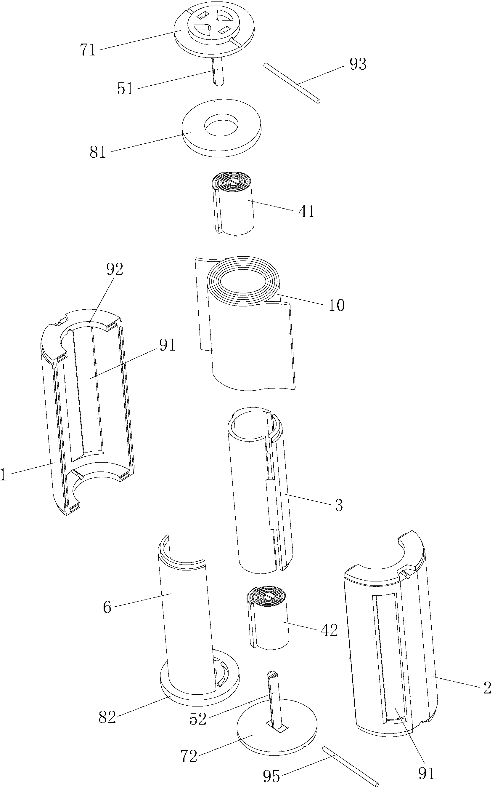
[0048] Please refer to Figures 15-18, Embodiment 2 of a flexible circuit board rolling and unwinding device of the present invention. The difference between this embodiment and Embodiment 1 is that the left housing 1 and the right housing 2 are equipped with a flexible circuit board 10 for winding. The window 90_1 placed at the time makes the outer casing formed by the left casing 1 and the right casing 2 a semi-open casing, and the semi-open casing is elliptical, and the front and rear axes of the elliptical semi-open casing The distance is greater than the left and right wheelbases, that is, the front-to-back distance is the long axis, and the left-right distance is the short axis, which is equivalent to cutting off a piece on the left and a piece on the right of the cylindrical shell. Wherein, the left housing 1 and the right housing 2 are provided with a semicircular limiting groove 90_2, and after the left housing 1 and the right housing 2 are fastened together, the limi...


PUM


Abstract

The invention relates to the technical field of coiling devices, in particular to a coiling device for a flexible circuit plate. The coiling device comprises a left casing, a right casing, a rotary plate, an upper volute spiral spring and a lower volute spiral spring. According to the coiling device, as an outer casing is formed through the mutual buckling of the left casing and the right casing, the left casing and the right casing are tightly adhered, the connecting area is enlarged, and the device is not easy to vertically split, so that the outer casing is stable and firm in structure; moreover, as the upper volute spiral spring and the lower volute spiral spring, as well as an upper central shaft and a lower central shaft are arranged symmetrically and form a balanced double-spring structure, when the flexible circuit plate stretches and retracts, the application of force and counter operation force of the springs when the springs are loosened or tightened are dispersed on the upper part and the lower part of the rotary plate in a balancing manner so as to balance the stress of the rotary plate, therefore, the rotary plate is smooth in rotation and not easy to damage.

Description

technical field [0001] The present invention relates to the technical field of winding and unwinding devices, in particular to a flexible circuit board (namely FPC, also known as flexible circuit board) winding and unwinding device. Background technique [0002] At present, the winding and unwinding device is usually used in the winding of wires for wired earphones, mice, keyboards, chargers and other products. For example, Chinese Patent No. 200620116285.6 discloses a single free-end wire reel, and Chinese Patent No. 200620116284.1 discloses a double free-end wire reel. The principle is that, through the scrolling elastic force of the scroll spring, the wire is wound up according to the helical path or the circular path, and when pulled out for use, the pulling force of the scroll spring causes the wire to be pulled out. The movement is slightly restrained, but the restraining force can still be easily overcome, so that this type of wire has a track path when it is retract...

Claims


Application Information

Patent Timeline
Patent Type & Authority Applications(China)
IPC IPC(8): B65H75/44B65H75/48
CPCB65H75/4471B65H75/28B65H75/486H02G11/02H05K1/028H05K3/361H05K2201/051
Inventor 陈益成
Owner DONGGUAN DADIAN ELECTRONICS
Why Eureka
Try Eureka