
The structure of the stop valve for the concealed valve body of the faucet

A faucet and stop valve technology, applied in the field of faucets, can solve the problems of increasing hotel maintenance costs, affecting the normal water use of residents in residential buildings, affecting the normal use of other shower rooms, etc., to facilitate maintenance and replacement, reduce maintenance costs, and have a simple, reasonable and compact structure Effect

Active Publication Date: 2017-02-15
开平市瑞霖淋浴科技有限公司
View PDF5 Cites 0 Cited by
  • Summary
  • Abstract
  • Description
  • Claims
  • Application Information

AI Technical Summary

Problems solved by technology

After the main part of the traditional concealed valve body of the faucet is buried in the wall, when the valve core is blocked due to water quality problems or the appearance of the faucet needs to be replaced, it is necessary to close the main valve of the water source before performing corresponding maintenance and replacement. In many residential areas, the main valve of the water source is a shared water valve. If the main valve of the water source is closed, it will affect the normal water use of the residents of the entire residential building; especially for modern hotels, the faucets in the shower rooms of each room are connected. A main valve controls the water source. Therefore, when the faucet of a certain shower room needs to be repaired and replaced, the main valve must be closed, which will greatly affect the normal use of other shower rooms and greatly increase the maintenance cost of the hotel.
Therefore, the structure of the concealed valve body of the faucet in the traditional technology needs to be further improved and optimized.

Method used


Image

  • The structure of the stop valve for the concealed valve body of the faucet
  • The structure of the stop valve for the concealed valve body of the faucet
  • The structure of the stop valve for the concealed valve body of the faucet

Examples


Embodiment Construction

[0015] The present invention will be described in further detail below in conjunction with the accompanying drawings and embodiments.

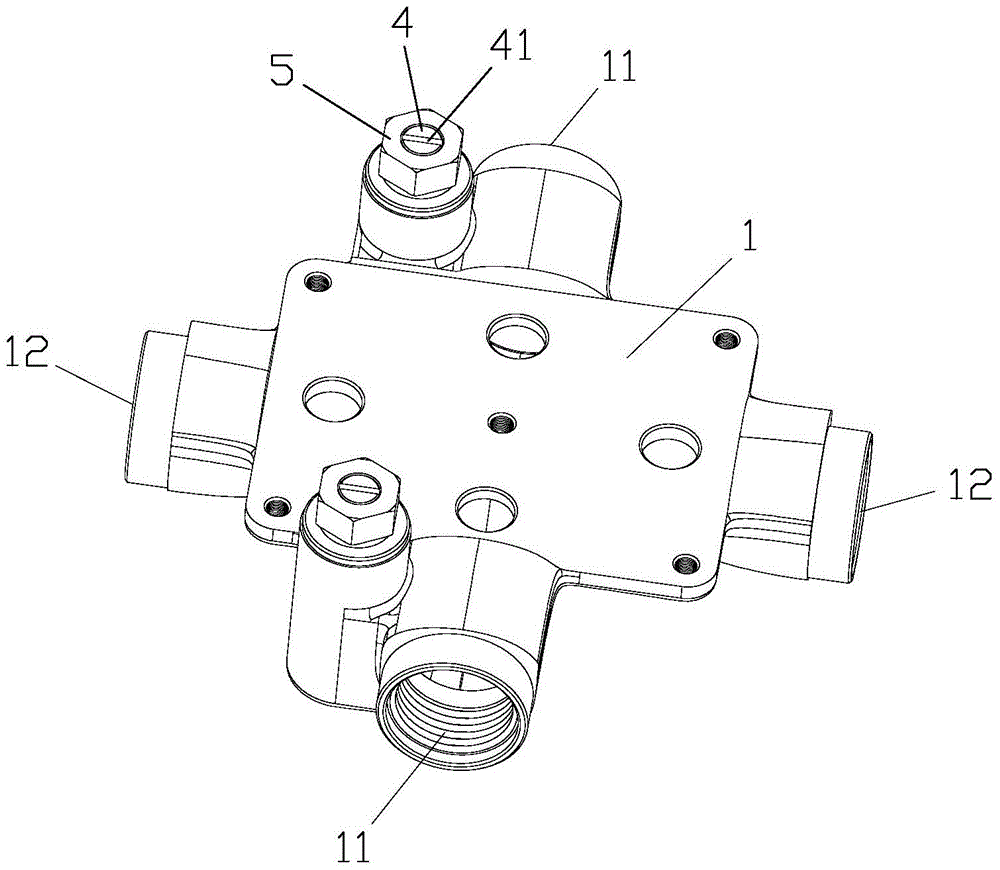
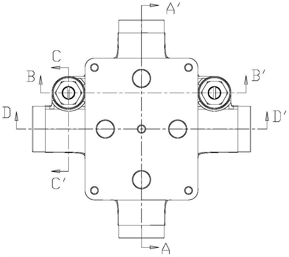
[0016] refer to Figure 1~Figure 8 , the stop valve structure of the concealed valve body of the faucet of the present invention includes a lower body 1 for installing a valve core (not shown), the lower body 1 is provided with a water inlet channel 11 and a water outlet channel 12, and the water inlet channel 11 is provided with a water retaining plate 13, the water retaining plate 13 is preferably integrally formed in the water inlet channel 11, the water retaining plate 13 includes a vertical plate 131, and the bottom end of the vertical plate 131 is first bent inward and backward The lower bend forms a bent relief portion 132, and the side of the water inlet channel 11 is provided with a diversion chamber 2 with an open top, and the diversion chamber 2 includes an upper diversion chamber 21 and a lower diversion chamber 22 , the upper div...


PUM


Abstract

The invention discloses a stop valve structure of a water faucet concealed installation valve body. The stop valve structure comprises a lower main body which is used for mounting a valve element, wherein a water inlet channel and a water outlet channel are formed in the lower main body; a water baffle is arranged in the water inlet channel and comprises a vertical plate; the bottom end of the vertical plate is inwards bent and then downwards bent to form a bending allowance part; flow guide cavities with opened top ends are arranged at the side edge positions of the water inlet channel; the flow guide cavities comprise an upper flow guide cavity and a lower flow guide cavity; the upper flow guide cavity is communicated with the water outlet channel; the lower flow guide cavity is communicated with the water inlet channel by the bending allowance part; baffles are arranged between the upper flow guide cavity and the lower flow guide cavity; water through holes are formed in the baffles and are used for communicating the upper flow guide cavity and the lower flow guide cavity; the top ends of the flow guide cavities are in threaded connection with push rods; sealing plugs are arranged at the bottom ends of the push rods; the sealing plugs can downwards move along with the pushing rods to seal the water through holes. Compared with the condition that a water source main valve needs to be closed in the prior art, the stop valve structure of the water faucet concealed installation valve body has the advantages that the maintenance and the replacement of valve element or water faucet appearance are greatly facilitated, and the maintenance cost is greatly reduced.

Description

technical field [0001] The invention relates to a faucet, in particular to a stop valve structure with a concealed valve body installed in the faucet. Background technique [0002] At present, most of the wall-mounted faucets in the bathroom adopt the wall-mounted type (that is, the concealed type), that is, the main body of the faucet is buried in the wall, and only the switch handle and the switch handle are exposed outside the wall. Because the installation is simple and convenient, it saves space. and so on are widely used. After the main part of the traditional concealed valve body of the faucet is buried in the wall, when the valve core is blocked due to water quality problems or the appearance of the faucet needs to be replaced, it is necessary to close the main valve of the water source before performing corresponding maintenance and replacement. In many residential areas, the main valve of the water source is a shared water valve. If the main valve of the water sou...

Claims


Application Information

Patent Timeline
Patent Type & Authority Patents(China)
IPC IPC(8): F16K11/072
CPCF16K43/001
Inventor 冯继君
Owner 开平市瑞霖淋浴科技有限公司
Learn More