
Valve rod

A valve stem and rod body technology, applied in the direction of valve devices, engine components, mechanical equipment, etc., can solve the problems of high flatness processing requirements, affecting sliding stability, shortening the life of valve stems, etc., to improve contact tightness and reduce contact area, the effect of increasing safety

Inactive Publication Date: 2014-07-30
江苏宇海环保设备有限公司
View PDF4 Cites 1 Cited by
  • Summary
  • Abstract
  • Description
  • Claims
  • Application Information

AI Technical Summary

Problems solved by technology

But the sliding head of existing valve stem, its side contacting with sliding seat is smooth surface, and contact area is big, has increased friction force on the one hand, shortens valve stem life-span, on the other hand in order to guarantee the contact between sliding head side and sliding seat In close contact, the smoothness processing of the corresponding side of the sliding head is highly required, which is usually difficult to guarantee, thus affecting the smoothness of sliding

Method used


Image

  • Valve rod
  • Valve rod
  • Valve rod

Examples


Embodiment 1

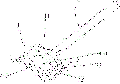
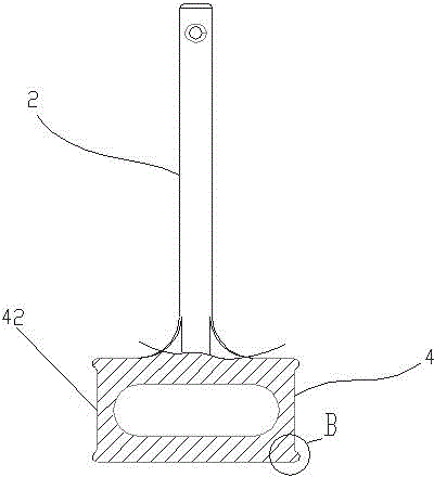
[0033] Such as Figure 1-3 As shown, a valve stem includes a cylindrical rod body 2 and a flat block-shaped sliding head 4 arranged at one end of the rod body 2 .

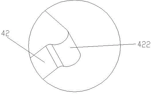
[0034] The sliding head 4 is symmetrical about the axis of the rod body 2 as a whole, and includes two first sides 42 respectively located on both sides of the rod body 2 and parallel to the axis of the rod body 2 . The two first sides 42 are respectively provided with outward protrusions 422 perpendicular to the first side 42 . Specifically, protrusions 422 are symmetrically provided at both ends of the first side 42 along the axial direction of the rod body 2 . The protrusion 422 is an arc-shaped protrusion protruding outward relative to the first side 42 where it is located. More specifically, the protrusion 422 has the same cross section at any position along the height direction of the first side 42, such as Figure 4 As shown, the cross-sectional profile is arc-shaped, preferably symmetrical arc-shaped.

...

Embodiment 2

[0039] As shown in the figure, a valve stem differs from Embodiment 1 in that the outer end surface 3 of the protrusion 422 is a plane.

Embodiment 3

[0041] As shown in the figure, a valve stem differs from Embodiment 1 in that the outer end surface of the rib 442 is an outwardly raised arc surface. More specifically, the ribs 442 have the same cross-section at any position along the circumferential direction, and the cross-sectional profile of the outer end is arc-shaped, preferably symmetrical arc-shaped.


PUM


Abstract

The invention relates to a valve rod. The valve rod comprises a rod body and a block-shaped sliding head arranged at one end of the rod body. The valve rod is characterized in that the sliding head comprises two first side surfaces which are respectively positioned at the two sides of the rod body and are parallel to the axis of the rod body; the first side surface is provided with an outward bulge vertical to the first side surface. The valve rod has the advantages that the bulge is ingeniously added on the first side surface on the basis of the traditional blocky head part, so that the contact area of the side surface with the corresponding surface of a matched sliding seat can be reduced, the contact compactness of the side surface and the sliding seat can be improved, further the sliding matching is more stable, the benefit for stable control of fluid is achieved, meanwhile, the service life of the valve rod also can be prolonged, the safety can be increased and the cost can be reduced.

Description

technical field [0001] The invention relates to a valve component, in particular to a valve stem. Background technique [0002] The valve stem is an important part of the valve. It is used for transmission. One end is connected to the actuator or handle, and the other end directly drives the valve core to move or rotate to realize the valve switch or adjustment function. The end of the valve stem connected to the actuator or the handle is a sliding head, which is usually set in the sliding seat, and the movement of the valve stem is guided by the cooperation and sliding of the valve stem head and the sliding seat. But the sliding head of existing valve stem, its side contacting with sliding seat all is smooth surface, and contact area is big, has increased friction force on the one hand, shortens valve stem life-span, on the other hand in order to guarantee the contact between sliding head side and sliding seat Close contact requires high processing requirements for the fla...

Claims


Application Information

Patent Timeline
Patent Type & Authority Applications(China)
IPC IPC(8): F16K51/00
CPCF16K51/00
Inventor 刘国华
Owner 江苏宇海环保设备有限公司
Learn More