
Spectral response measurement method and system of optical device

A spectral response and measurement system technology, applied in the measurement system, optical device spectral response measurement method, and optical device measurement field, can solve the problems of narrow measurement bandwidth, low measurement dynamic range, and high cost of measurement devices, and achieve high precision The effect of measurement, simple structure and low manufacturing cost

Active Publication Date: 2014-07-30
NANJING UNIV OF AERONAUTICS & ASTRONAUTICS
View PDF5 Cites 20 Cited by
  • Summary
  • Abstract
  • Description
  • Claims
  • Application Information

AI Technical Summary

Problems solved by technology

However, the above method needs to use a broadband microwave amplitude and phase receiving module to extract the amplitude and phase of the radio frequency signal, which makes the entire measurement device expensive
In addition, the above method also has problems such as the inability to measure the bandpass optical device under test, the narrow measurement bandwidth (limited by the bandwidth of the electro-optic modulator, less than 40 GHz), and the low dynamic range of the measurement.

Method used


Image

  • Spectral response measurement method and system of optical device
  • Spectral response measurement method and system of optical device
  • Spectral response measurement method and system of optical device

Examples


Embodiment Construction

[0020] The technical scheme of the present invention is described in detail below in conjunction with accompanying drawing:

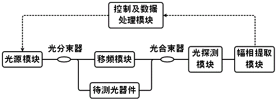
[0021] The idea of ​​the invention is to realize the measurement of the spectral response of the optical device by combining the photon frequency shifting technology and the radio frequency signal amplitude and phase extraction technology. Specifically, the single-wavelength sweeping optical signal is first divided into two paths, one path is optically frequency-shifted, and the other path is transmitted through the optical device to be tested; then the two paths of optical signals are beaten to convert the spectral response information of the optical device to the electrical domain; and then use the RF amplitude and phase extraction technology to extract the spectral response information of the optical device, so as to realize the spectral response measurement of the optical device.

[0022] figure 1 A structure of the optical device spectral response...


PUM


Abstract

The invention discloses a spectral response measurement method of an optical device and belongs to the technical field of optical measurement. According to the method, optical detection signals of the single wavelength are divided into two paths, frequency shifting with the fixed frequency shifting amount is carried out on one path of signals, and the other path of signals pass through the optical device to be detected; then frequency beat is carried out on the two paths of light, and radio-frequency signals carrying the spectral response information of the optical device to be detected at the optical detection signal frequency positions are obtained; a radio-frequency amplitude phase extraction device with the same working efficiency and the frequency shifting amount is used for extracting the amplitude phase information of the radio-frequency signals, and the amplitude frequency response and phase frequency response of the optical device to be detected at the optical detection signal frequency positions are obtained; the wavelength of the optical detection signals is changed, the process is carried out repeatedly, and the spectral vector response information of the optical device to be detected is obtained. The invention further discloses a spectral response measurement system of the optical device. Compared with the prior art, the spectral response measurement method and system of the optical device have the advantages of being capable of achieving the high-precision measurement of the amplitude frequency response and phase frequency response of the optical device and greatly lowering cost at the same time.

Description

technical field [0001] The invention relates to a method for measuring an optical device, in particular to a method for measuring the spectral response of an optical device and a measurement system, and belongs to the technical field of optical measurement. Background technique [0002] With the rapid development and continuous improvement of photonic technology, the development of high-precision optical devices and the application of existing high-precision optical devices (such as microrings, microspheres, etc.) Fine optical device spectral response testing technology. However, the existing optical device spectral response technology is difficult to perform multi-dimensional and high-precision characterization of the above-mentioned high-precision spectral response. The only commercial optical device multi-dimensional spectral response measuring instrument is the OVA5000 launched by the American LUNA company, which can measure the multi-dimensional spectral response of op...

Claims


Application Information

Patent Timeline
Patent Type & Authority Applications(China)
IPC IPC(8): G01J3/28
Inventor 潘时龙薛敏唐震宙赵永久张方正朱丹
Owner NANJING UNIV OF AERONAUTICS & ASTRONAUTICS
Learn More