Spring energy storage type horizontal impact test stand and method
A technology of impact test and spring energy storage, which is applied in the direction of impact test, machine/structural component test, measuring device, etc. It can solve the problems of heavy weight, complex structure and high cost of the impact table, so as to prolong the service life and increase the degree of automation , the effect of avoiding damage
- Summary
- Abstract
- Description
- Claims
- Application Information
AI Technical Summary
Problems solved by technology
Method used
Image


Examples
Embodiment 1
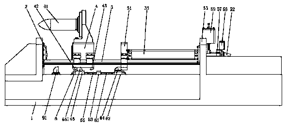
[0051] Such as figure 1 , 2 , 3, the spring energy storage type horizontal impact test bench provided in this embodiment includes: a base 1, a waveform generator 2, a guide rail 3, an impact table 4 for fixing an experimental product 41, and an ejection mechanism;
[0052] Both ends of the base 1 are respectively equipped with a waveform generator 2 and an ejection mechanism;
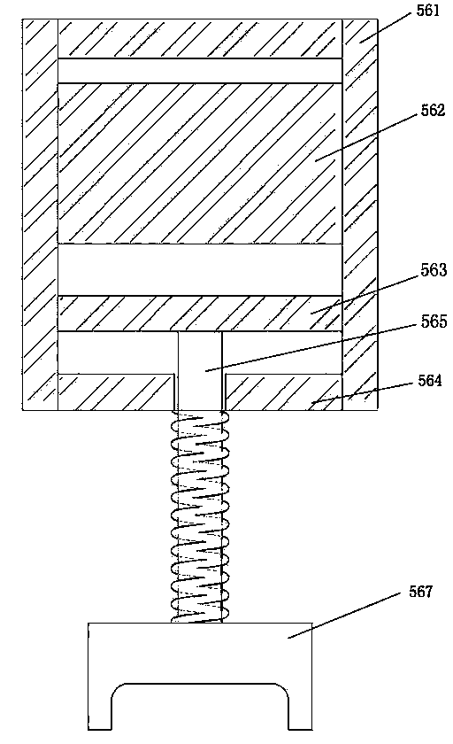
[0053] The ejection mechanism includes a push plate 51, a spring pull rod 52, a mounting plate 53, an energy storage spring 54, a compression cylinder 55, a locking mechanism 156, and a cylinder pull rod 57;
[0054] A guide rail 3 parallel to the axial direction of the test bench is provided between the waveform generator 2 and the mounting plate 53 of the ejection mechanism; the push plate 51 is installed on the guide rail 3 and can be fed along the guide rail 3; The impact table 4 described above is installed on the guide rail 3, between the push plate 51 and the waveform generator 2, and can be fe...
Embodiment 2
[0065] Such as Figure 1~3 As shown, the spring energy storage type horizontal impact test bench provided in this embodiment includes: a bottom base 1, a waveform generator 2, a guide rail 3, an impact table 4 for fixing an experimental product 41, and an ejection mechanism;
[0066] Both ends of the base 1 are respectively equipped with a waveform generator 2 and an ejection mechanism;
[0067] The ejection mechanism includes a push plate 51, a spring pull rod 52, a mounting plate 53, an energy storage spring 54, a compression cylinder 55, a locking mechanism 156, and a cylinder pull rod 57;
[0068] A guide rail 3 parallel to the axial direction of the test bench is provided between the waveform generator 2 and the mounting plate 53 of the ejection mechanism; the push plate 51 is installed on the guide rail 3 and can be fed along the guide rail 3; The impact table 4 described above is installed on the guide rail 3, between the push plate 51 and the waveform generator 2, and...
PUM
 Abstract
Description
Claims
Application Information