
Control devices for internal combustion engines

A technology of a control device and an internal combustion engine, applied in engine control, internal combustion piston engine, combustion engine, etc., can solve problems such as torque fluctuation, deterioration of backflow exhaust, misfire, etc., and achieve the effect of suppressing exhaust deterioration

Active Publication Date: 2016-07-06
HITACHI ASTEMO LTD
View PDF8 Cites 0 Cited by
  • Summary
  • Abstract
  • Description
  • Claims
  • Application Information

AI Technical Summary

Problems solved by technology

[0009] However, in an internal combustion engine generally equipped with a supercharger, in a structure in which the exhaust gas is returned to the upstream portion of the compressor, there is a phenomenon that the path from the junction of the exhaust gas and fresh air to the cylinder is long, During the transition, the air bypass valve of the air bypass passage that connects the compressor up and down, etc., causes the exhaust gas volume to temporarily increase or decrease during the transition such as deceleration operation and acceleration operation, and the exhaust gas volume will be reduced. Unable to import stably into target value
Therefore, due to the inappropriate recirculation of the exhaust gas, the deterioration of the exhaust gas due to the fluctuation of the air-fuel ratio and the fluctuation of the torque occur, and in the worst case, even the problem of misfire occurs.

Method used


Image

  • Control devices for internal combustion engines
  • Control devices for internal combustion engines
  • Control devices for internal combustion engines

Examples


Embodiment 1

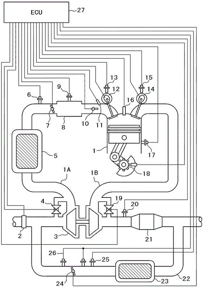
[0043] exist figure 1 Among them, reference numeral 1 is an internal combustion engine to be controlled, and the internal combustion engine 1 communicates with an intake flow path 1A and an exhaust flow path 1B.

[0044] An air flow sensor 2 including an intake air temperature sensor is incorporated in the intake air flow path 1A. A turbocharger 3 is arranged in the intake flow path 1A and the exhaust flow path 1B. The compressor of the supercharger 3 is connected to the intake flow path 1A, and the turbine is connected to the exhaust flow path 1B.

[0045] The supercharger 3 includes: a turbine for converting energy of exhaust gas into rotational motion of turbine blades; and a compressor for compressing intake air by rotation of compressor blades coupled to the turbine blades. An intercooler 5 for cooling the temperature of the intake air which has been raised by adiabatic compression is provided downstream of the compressor side of the supercharger 3 .

[0046] An intake ...

Embodiment 2

[0141] In the first embodiment described above, the angle of action of the intake valve 12, the so-called lift amount, is changed in order to control the intake amount. In contrast to this, in other embodiments described below, the use of the throttle valve 7 is shown. to control the volume of inhalation.

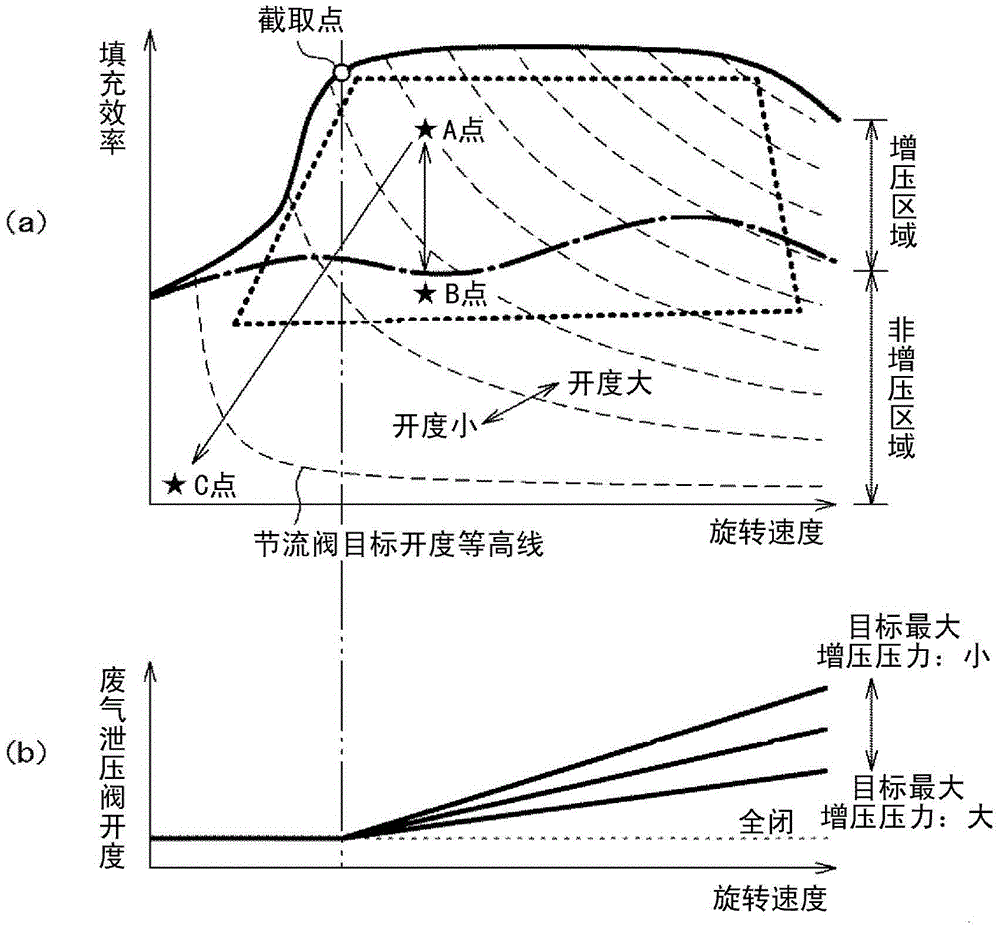
[0142] Figure 18 It is a diagram explaining the correspondence relationship between the throttle valve 7 and the wastegate valve 19 in the steady-state target opening degrees in an internal combustion engine including a supercharger.

[0143] Figure 18 (a) shows the corresponding relationship of the steady-state target opening degree of the throttle valve 7. In the non-supercharged region, the opening degree of the throttle valve 7 increases with the increase of the intake air amount. On the other hand, in the supercharged region, the opening degree of the throttle valve 7 In the region, the throttle valve 7 is fully opened to perform load control based on the superchar...


PUM


Abstract

The invention provides a control device for an internal combustion engine. There are the following phenomena: due to the long path from the confluence of EGR and fresh air to the cylinder, and the air bypass valve of the air bypass passage connecting the upper and lower sides of the compressor opens during deceleration, etc., the During deceleration operation, the amount of exhaust gas temporarily increases, so that the amount of exhaust gas cannot be introduced stably to the target value. In an internal combustion engine in which the exhaust gas flows from the downstream part of the turbine to the upstream part of the compressor, in the supercharged state and the exhaust gas recirculation state, the air bypass valve bypassing the compressor is closed during deceleration operation. state and open the wastegate bypassing the turbo.

Description

technical field [0001] The present invention relates to a control device for an internal combustion engine that returns exhaust gas flowing from a downstream portion of an exhaust-side turbine to an upstream portion of an intake-side compressor after being cooled by a cooler. A control device for an internal combustion engine that controls the flow of exhaust gas by recirculating appropriate exhaust gas during operation. Background technique [0002] In recent internal combustion engines, a supercharger is used to pressurize the air supplied to the internal combustion engine from the viewpoint of downsizing, low fuel consumption, and low exhaust gas. As such an internal combustion engine using a supercharger is known in JP It is described in Publication No. 2009-250209 (Patent Document 1). [0003] Patent Document 1 discloses a technique in which, in an internal combustion engine equipped with a variable valve mechanism and a supercharger, an exhaust gas flowing from an ups...

Claims


Application Information

Patent Timeline
Patent Type & Authority Patents(China)
IPC IPC(8): F02D21/08F02D13/02F02D23/00
CPCF02M26/05Y02T10/12F02D13/02F02D21/08F02D23/00F02B37/22
Inventor 铃木邦彦浅野诚二
Owner HITACHI ASTEMO LTD
Learn More