Internal combustion engine controller
一种控制装置、内燃机的技术,应用在发动机控制、燃料喷射控制、内燃活塞发动机等方向,能够解决无法实现驾驶者车辆动作、转矩过调、无法实现车辆动作等问题
- Summary
- Abstract
- Description
- Claims
- Application Information
AI Technical Summary
Problems solved by technology
Method used
Image
Examples
Embodiment approach 1
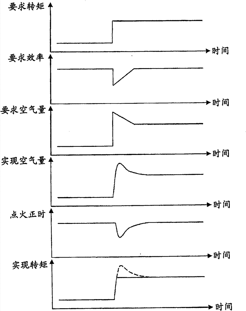
[0035] use figure 1 and figure 2 Embodiment 1 of the present invention will be described.
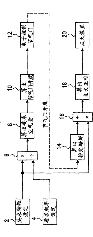
[0036] figure 1 It is a block diagram showing the configuration of a control device for an internal combustion engine according to Embodiment 1 of the present invention. The control device of this embodiment is a control device suitable for a spark ignition type internal combustion engine. The control device of the present embodiment controls the torque of the internal combustion engine by operating an electronically controlled throttle valve (hereinafter, simply referred to as "throttle valve") 12 as an intake actuator and an ignition device 20 .
[0037] The control device of the present embodiment includes a required torque setting unit 2 for setting a required value of torque of the internal combustion engine. The requested torque setting unit 2 considers ECT (Electronic Controlled Transmission), VSC (Vehicle Stability Control System) and the like in addition to the torque requ...
Embodiment approach 2
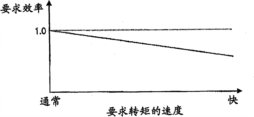
[0059] use image 3 Embodiment 2 of the present invention will be described.
[0060] The overall structure of the control device of this embodiment is the same as that of Embodiment 1, by figure 1 block diagram to represent. The control device of the present embodiment differs from the control device of the first embodiment in that the required efficiency setting unit 4 has a function as "means for correcting the required efficiency".
[0061] In the present embodiment, when the set value of the required torque increases sharply, the required efficiency setting unit 4 makes the set value of the required efficiency relative to the previous one in accordance with the timing of the sharp increase of the set value of the required torque. Temporary reduction when a set value is reached. However, the present embodiment differs from the first embodiment in the setting of the amount of decrease to temporarily decrease the set value of the required efficiency. In the present embod...
Embodiment approach 3
[0066] use Figure 4 Embodiment 3 of the present invention will be described.
[0067] Figure 4 It is a block diagram showing the configuration of a control device for an internal combustion engine according to Embodiment 3 of the present invention. exist Figure 4 in, with figure 1 Components common to the control device according to Embodiment 1 shown are denoted by the same reference numerals. Compare figure 1 and Figure 4 It can be seen that the difference between the control device of this embodiment and the control device of Embodiment 1 is that the required torque and the required efficiency are respectively supplied from the outside of the control device. Here, the required torque and the required efficiency are respectively supplied from a powertrain management system (Power Train Manager, hereinafter referred to as “PTM”) (not shown) that collectively controls the entire drive system of the vehicle. The control device and PTM according to the present embodim...
PUM
 Abstract
Description
Claims
Application Information
 - R&D
- Intellectual Property
- Life Sciences
- Materials
- Tech Scout
- Unparalleled Data Quality
- Higher Quality Content
- 60% Fewer Hallucinations
Browse by: Latest US Patents, China's latest patents, Technical Efficacy Thesaurus, Application Domain, Technology Topic, Popular Technical Reports.
© 2025 PatSnap. All rights reserved.Legal|Privacy policy|Modern Slavery Act Transparency Statement|Sitemap|About US| Contact US: help@patsnap.com


