Method, device and system for wireless access
A wireless access, together technology, applied in the field of communications, can solve problems such as inability to work, poor site availability, and inability to achieve disaster recovery.
- Summary
- Abstract
- Description
- Claims
- Application Information
AI Technical Summary
Problems solved by technology
Method used
Image
Examples
Embodiment 1
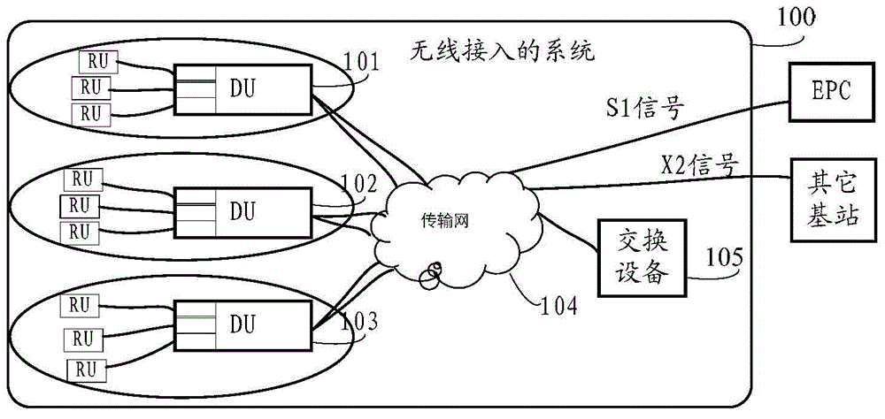
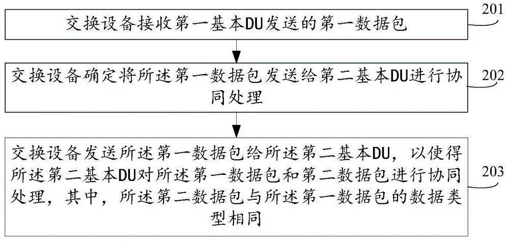
[0237] An embodiment of the present invention provides a wireless access method, the method is applied to switching equipment, in which the basic digital output unit DU is deployed in the site, specifically in the wireless access corresponding to the LTE network as shown in 1 System 100 is described below, assuming figure 1 The wireless access system 100 shown includes three basic DUs, respectively DU101, DU102, and DU103. The system 100 also includes a radio frequency processing unit (Radio process unit, RU), a transmission network 104, and a switching device 105. figure 2 As shown, the method includes:
[0238] 201. The switching device receives a first data packet sent by a first basic DU.
[0239] Specifically, the embodiment of the present invention does not specifically limit the number of the first basic DU, which may be one or several, and any basic DU with the technical characteristics of the first basic DU in the embodiment of the present invention may be It is ca...
Embodiment 2
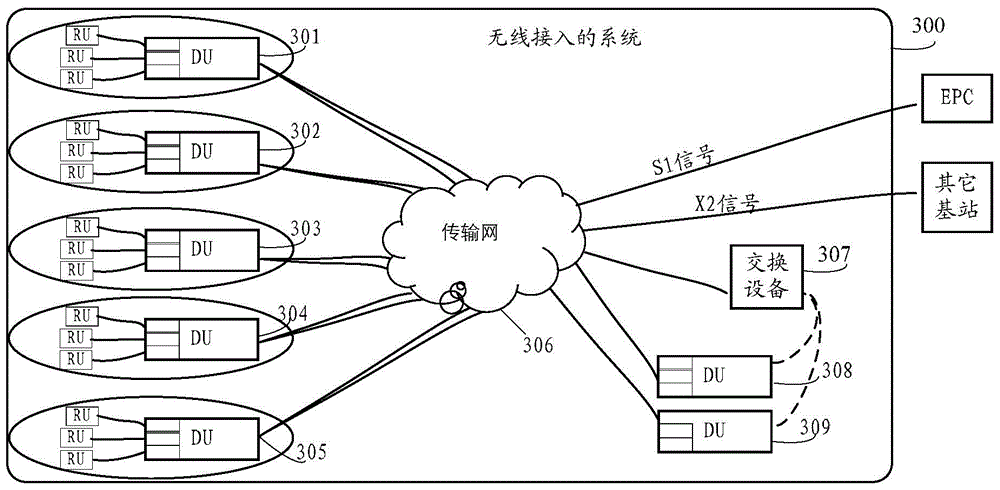
[0327] An embodiment of the present invention provides a wireless access method, the method is applied to switching equipment, in which the basic digital output unit DU is deployed in the site, specifically in the wireless access corresponding to the LTE network as shown in 3 System 300 is described, as Figure 12 As shown, the method includes:
[0328] 1201. The switching device receives a first data packet sent by a first basic DU.
[0329] Specifically, the embodiment of the present invention does not specifically limit the number of the first basic DU, which may be one or several, and any basic DU with the technical characteristics of the first basic DU in the embodiment of the present invention may be It is called the first basic DU.
[0330] Exemplary, in image 3 , the first basic DU can be DU301, DU302, or DU301 and DU302.
[0331] It should be noted that the "first" in the first data packet has no special meaning, and is only used to distinguish it from the "secon...
Embodiment 3
[0606] An embodiment of the present invention provides a switching device 2000, specifically as Figure 20 As shown, the switching device 2000 includes a receiving unit 2001 , a determining unit 2002 , and a sending unit 2003 .
[0607] The receiving unit 2001 is configured to receive a first data packet sent by a first basic digital processing unit DU, and send the first data packet to the determining unit 2002, wherein the basic DU is deployed in a site.
[0608] The determining unit 2002 is configured to receive the first data packet sent by the receiving unit 2001, and determine to send the first data packet to the second basic DU for collaborative processing, and then send the first data packet to the sending unit 2003.
[0609] The sending unit 2003 is configured to receive the first data packet sent by the determining unit 2002, and send the first data packet to the second basic DU, so that the second basic DU is Cooperative processing is performed on the first data p...
PUM
 Abstract
Description
Claims
Application Information
 - R&D
- Intellectual Property
- Life Sciences
- Materials
- Tech Scout
- Unparalleled Data Quality
- Higher Quality Content
- 60% Fewer Hallucinations
Browse by: Latest US Patents, China's latest patents, Technical Efficacy Thesaurus, Application Domain, Technology Topic, Popular Technical Reports.
© 2025 PatSnap. All rights reserved.Legal|Privacy policy|Modern Slavery Act Transparency Statement|Sitemap|About US| Contact US: help@patsnap.com


