System composed of all-wing unmanned planes capable of making wings oblique and connected in parallel through coupling of wingtips

A technology of unmanned aerial vehicles and flying wings, applied in the field of unmanned aerial vehicle systems, can solve the problems of aircraft attitude control and track control difficulties, and achieve the effect of improving the lift-to-drag ratio

Active Publication Date: 2014-08-06
XIAN AIRCRAFT DESIGN INST OF AVIATION IND OF CHINA
View PDF8 Cites 18 Cited by
  • Summary
  • Abstract
  • Description
  • Claims
  • Application Information

AI Technical Summary

Problems solved by technology

When entering a high-intensity confrontation environment to perform defense penetration and strike missions, UAVs prefer to have supersonic flight capabilities, and the large-aspect-ratio straight-wing flying wing layout is completely unsuitable for supersonic flight, so people consider adopting Flying

Method used


Image

  • System composed of all-wing unmanned planes capable of making wings oblique and connected in parallel through coupling of wingtips
  • System composed of all-wing unmanned planes capable of making wings oblique and connected in parallel through coupling of wingtips
  • System composed of all-wing unmanned planes capable of making wings oblique and connected in parallel through coupling of wingtips

Examples


Embodiment 1

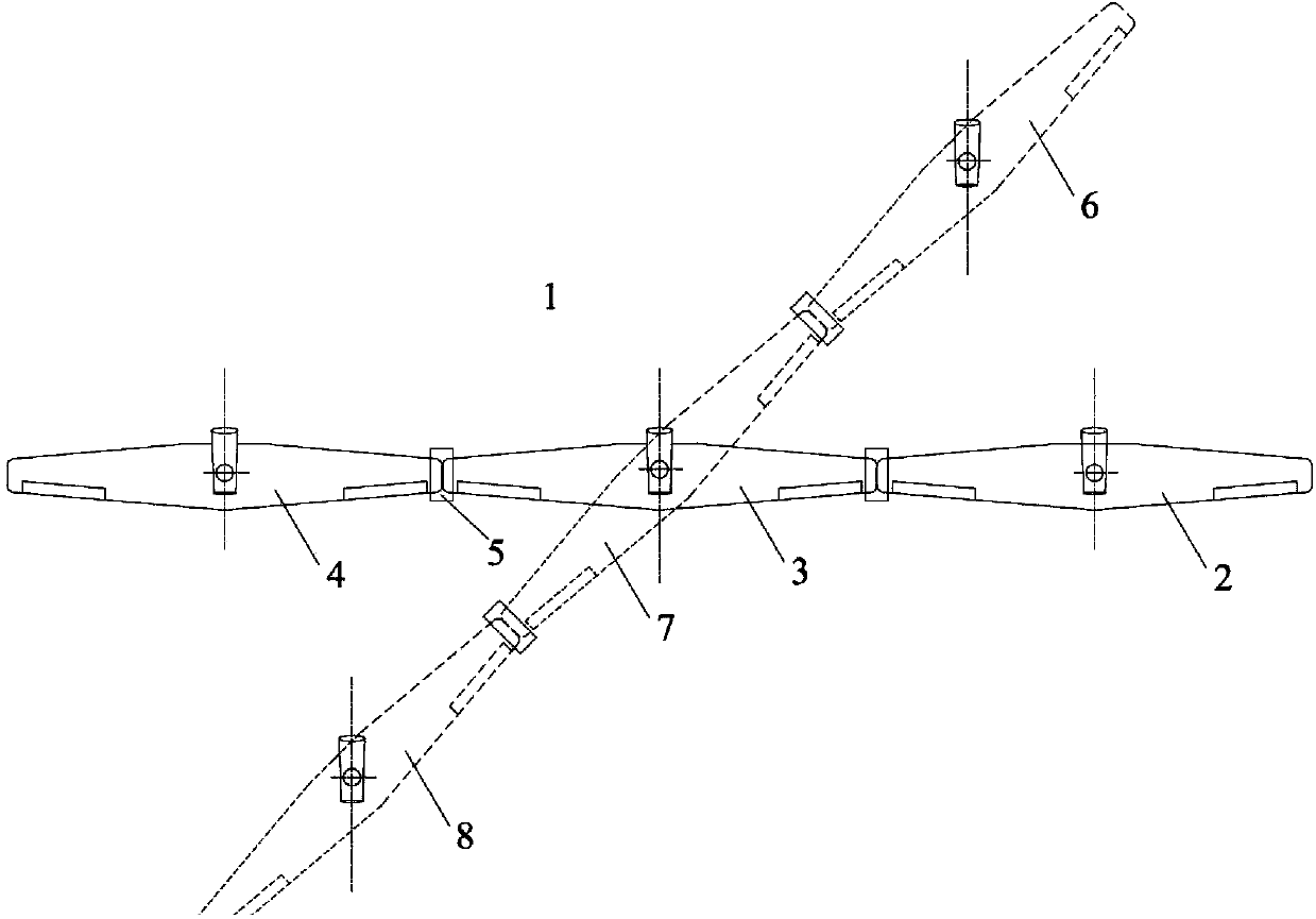
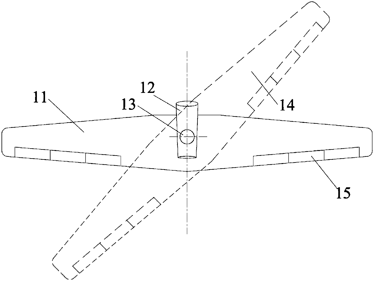
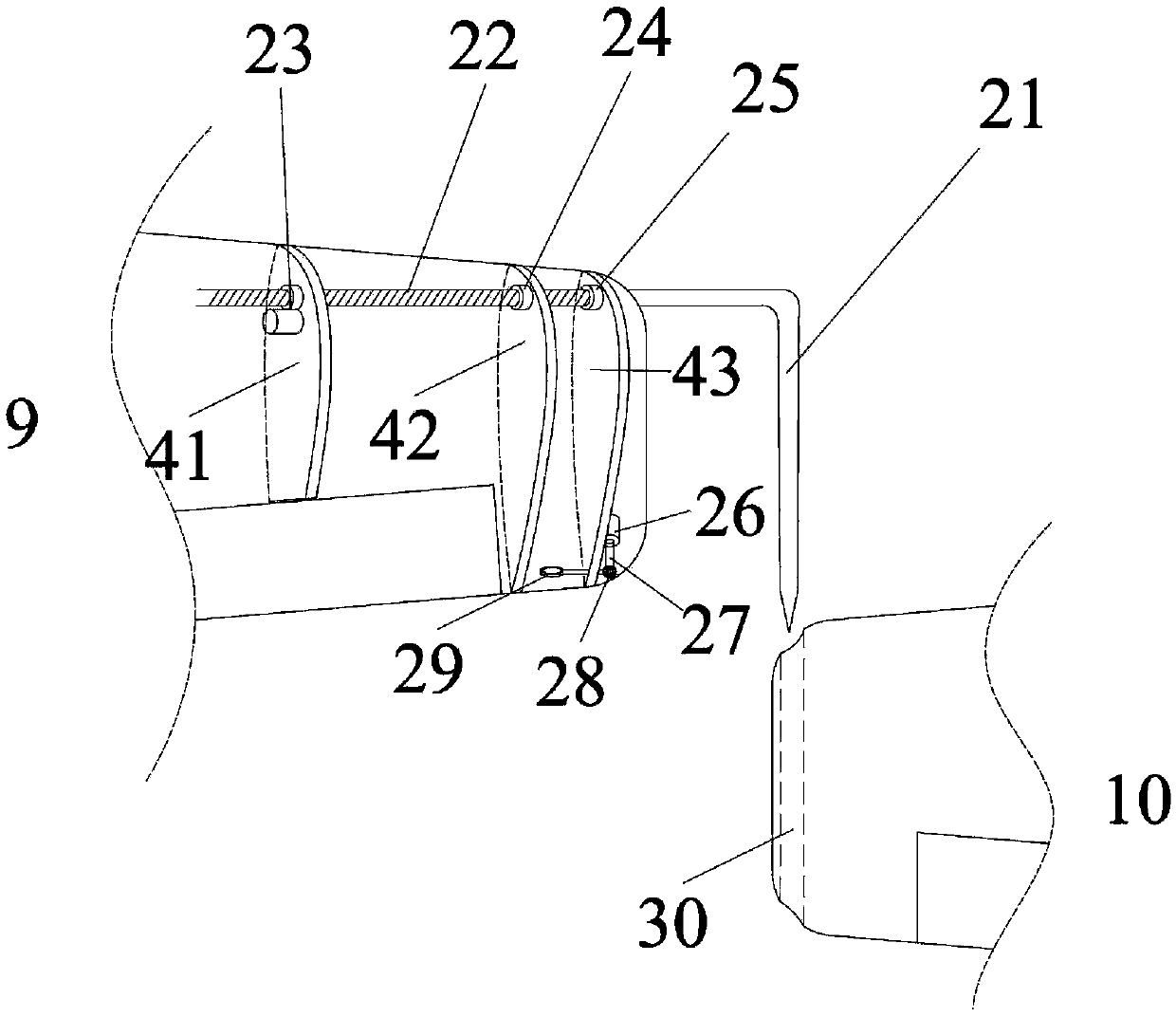
[0027] Embodiment 1: see figure 1 , is a schematic diagram of a parallel flying-wing unmanned aerial vehicle system with tiltable wings connected to the wingtips. In the parallel flying-wing unmanned aerial vehicle system 1, 2, 3, and 4 from right to left represent three planes with the same shape. For the same flying-wing UAV, the area designated by box 5 represents the docking mechanism between the flying-wing UAV 2 and the flying-wing UAV 3, and the following will be based on image 3 and Figure 4 Make an introduction. The dotted-line wings 6, 7, and 8 are illustrations when the parallel flying-wing UAV system 1 is in the oblique state. At this time, the individual flying-wing UAVs 6, 7, and 8 are all at an inclination angle between the engine and the wing. status.

[0028] In the present invention, the number of the same flying-wing drones may be equal to but not limited to three. Each flying-wing UAV adopts a modular design, that is, each UAV has the same aircraft pl...


PUM


Abstract

The invention relates to the technical field of layout design of unmanned plane systems, specifically to an unmanned plane system combined with all-wing oblique wing planes by using a wingtip connecting/towing technology. The unmanned plane system is composed of the plural identical all-wing unmanned planes which are connected in parallel through a wingtip-coupling mode. Wings and an engine of each unmanned plane can rotate relative to each other around a rotating shaft in the horizontal direction. The wingtip-coupling mode is that the left and right wingtips of each all-wing unmanned plane are provided with corresponding wingtip coupling and towing mechanisms, and every two coupled all-wing unmanned planes are only capable of doing relative movements of rotating around a coupling shaft. The system can increase the lift-drag ratio effectively and enable each unmanned plane to achieve a longer flying range and better endurance. Moreover, the flight capabilities in a middle-low speed zone, a subsonic speed zone, and an ultrasonic speed zone are all taken into account. When necessary, the in-flight detachment or recombination of the planes can be realized according to the actual situations, such as task requirements or atmospheric conditions.

Description

technical field [0001] The invention relates to the technical field of layout design of an unmanned aerial vehicle system, and specifically relates to an unmanned aerial vehicle system that combines wingtip connection / drag technology with a flying-wing oblique aircraft. Background technique [0002] In the past, wingtip docking / tow techniques were developed and flight tested with the C-47 / Q-14; figure 1 The flying-wing oblique-wing layout aircraft as seen. [0003] In the 1940s and 1950s, people developed wingtip docking / tow technology and used C-47 / Q-14 for flight tests. The concept of wingtip docking / dragging technology was proposed by German scientist Dr. Richard Vogt. Add two "free-floating" extensions to the wingtips of the aircraft to store extra fuel to increase the range of the aircraft. The core of its design idea is to enable the expansion section to perform limited movement relative to the connection point, so that the weight of the expansion section itself can...

Claims


Application Information

Patent Timeline
IPC IPC(8): B64C39/00B64C30/00
Inventor 李梓衡梅红陈晓静盛慧方力
Owner XIAN AIRCRAFT DESIGN INST OF AVIATION IND OF CHINA
Why Eureka
Try Eureka