Mechanical centering device for tire conveying line

A technology of centering device and conveyor line, which is applied to conveyor objects, transportation and packaging, etc., can solve the problems of high labor intensity, conveyor belt deviation, bumping, etc. Effect

Inactive Publication Date: 2014-08-06
SHANGHAI JIAZHENG MACHINERY
View PDF7 Cites 10 Cited by
  • Summary
  • Abstract
  • Description
  • Claims
  • Application Information

AI Technical Summary

Problems solved by technology

[0002] There are many quality testing items for finished tires, and the testing equipment used is arranged according to the arrangement of the technological process. Most of them are scattered and not centralized. The way of conveying the finished products is usually manpower supplemented by simple handling tools and equipment. Ordinary belt conveyors are used as a means to complete the product, which is prone to collisions and bumps during transportation and transportation, which will affect product quality and also affect the production efficiency of inspection work.
However, in the tire transportation, there is a problem that the tire is not in the middle of the conveying line, which causes the tire to appear left and right during the conveying process, leaning on one side, and the conveying is not smooth, which will also cause the conveyor belt to deviate and affect the service life of the conveying equipment. , where tires are sorted, sorting is difficult

Method used


Image

  • Mechanical centering device for tire conveying line
  • Mechanical centering device for tire conveying line

Examples


Embodiment

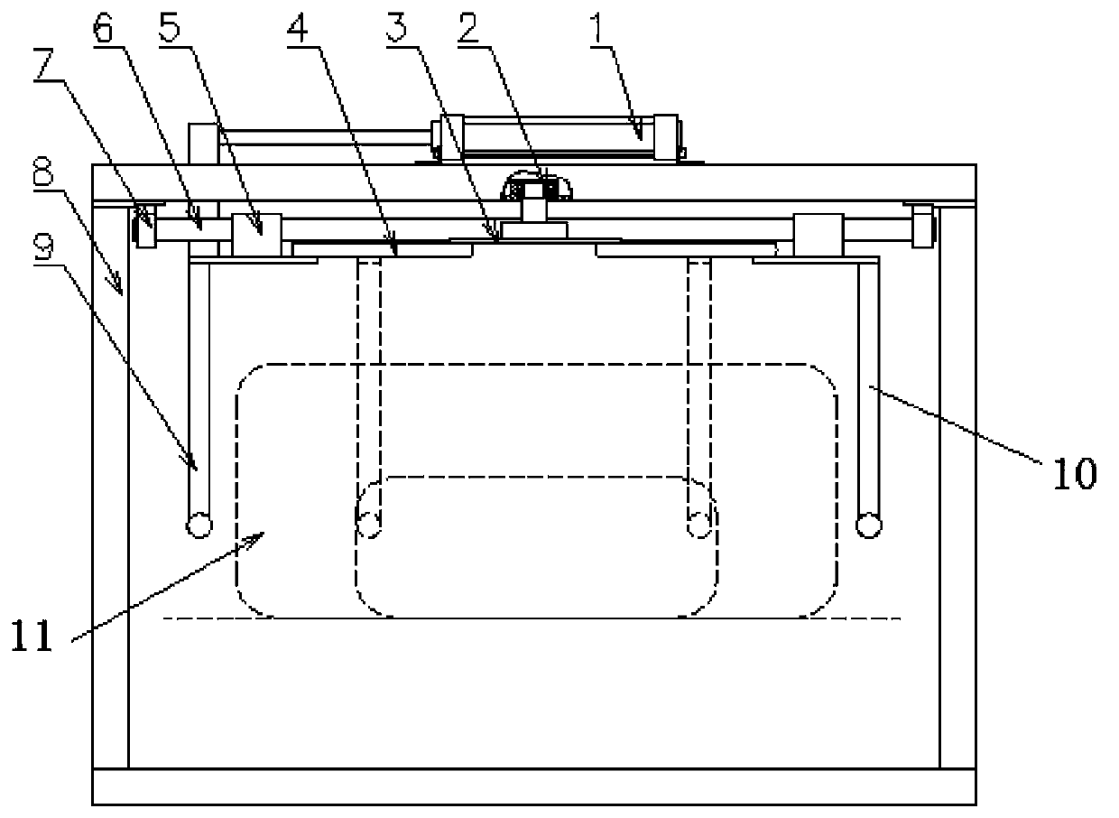
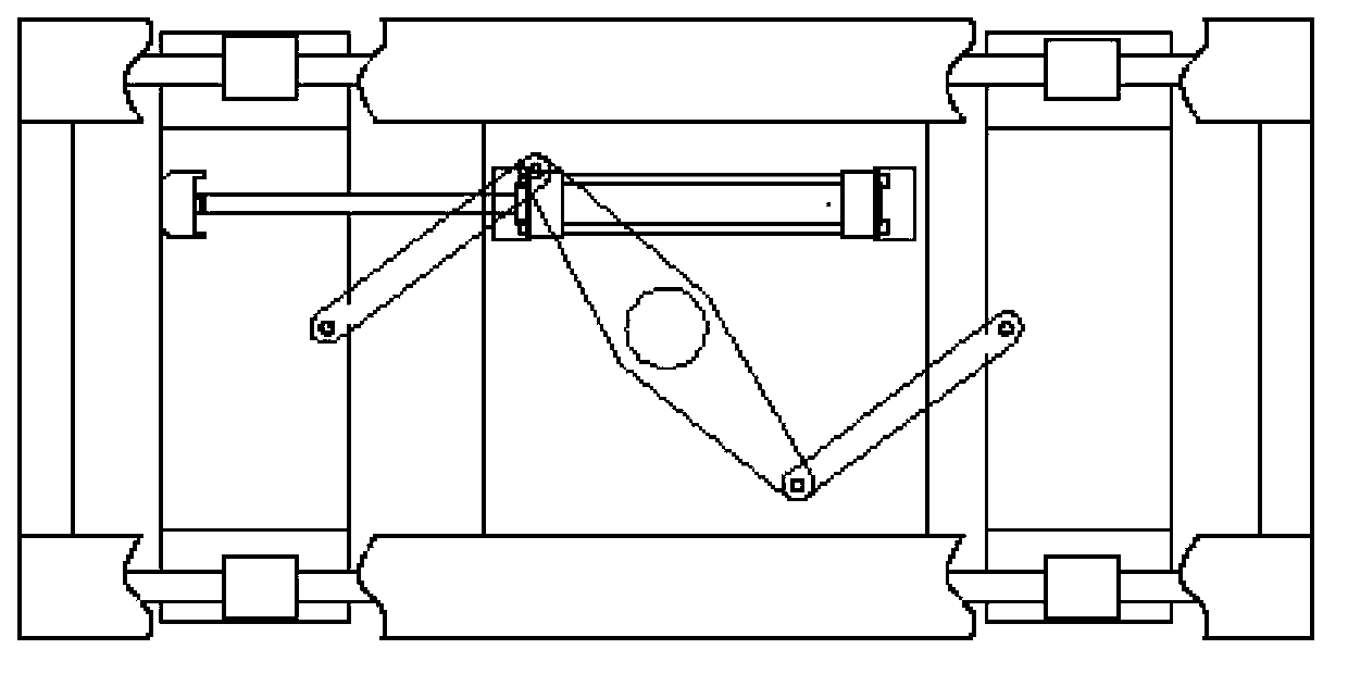
[0018] Such as figure 1 , figure 2 As shown, a mechanical centering device for a tire conveying line includes a cylinder 1, a cantilever mechanism 3, a slider 5, a guide rail 6, a guide rail fixing seat 7, a frame 8, an active clamping arm 9 and a driven clamping arm 10. The cylinder 1, the cantilever mechanism 3, and the guide rail fixing seat 7 are all fixed on the frame 8, the cylinder 1 is in transmission link with the active clamping arm 9, and the active clamping arm 9 and the driven clamping arm 9 are connected The arms 10 are all connected to the slider 5, the slider 5 is installed on the guide rail 6, the guide rail 6 is fixed on the guide rail fixing seat 7, and the active clamping arm 9 is driven by the cantilever mechanism 3 to be driven and clamped. arm 10 movement;

[0019] When the tire is centered, the cylinder 1 drives the active clamping arm 9 to move to the middle, and the active clamping arm 9 drives the driven clamping arm 10 to move to the middle at th...


PUM


Abstract

The invention relates to a mechanical centering device for a tire conveying line. The mechanical centering device comprises a cylinder (1), a suspension mechanism (3), a slider (5), a guide rail (6), a guide rail fixing seat (7), a frame (8), an active clamping arm (9) and a driven clamping arm (10). The cylinder (1), the suspension mechanism (3) and the guide rail fixing seat (7) are all fixed to the frame (8), the cylinder (1) is connected to the active clamping arm (9) in a transmission manner, the active clamping arm (9) and the driven clamping arm (10) are both connected to the slider (5) which is mounted on the guide rail (6), the guide rail (6) is fixed to the guide rail fixing seat (7), and the active clamping arm (9) drives the driven clamping arm (10) to move through the suspension mechanism (3). Compared with the prior art, the mechanical centering device has the advantages that structure is compact, mounting is facilitated, the adopting range is broad, and the mechanical centering device is safe and reliable to use.

Description

technical field [0001] The invention relates to a tire conveying device, in particular to a mechanical centering device for a tire conveying line. Background technique [0002] There are many quality testing items for finished tires, and the testing equipment used is arranged according to the arrangement of the process flow. Most of the systems are scattered and not centralized. The delivery method of the finished products is generally supplemented by manpower, simple handling tools and Ordinary belt conveyors are used as a means to complete the product, which is prone to collisions and bumps during transportation and transportation, which will affect product quality and also affect the production efficiency of inspection work. The labor intensity is high, but it is also conveyed through an automated tire conveyor line . However, in the tire transportation, there is a problem that the tire is not in the middle of the conveying line, which causes the tire to appear left and ...

Claims


Application Information

Patent Timeline
Patent Type & Authority Applications(China)
IPC IPC(8): B65G47/22
Inventor 林志贤林康伟
Owner SHANGHAI JIAZHENG MACHINERY
Why Eureka
Try Eureka