Slip sheet expander

A technology of expander and sliding vane, which is applied in the direction of mechanical equipment, engine components, machines/engines, etc., which can solve the problem of increased friction power consumption of sliding vanes, straining the cylinder, and failure to realize the sliding vane expander without initial rotation. Start-up and other problems, to achieve the effect of miniaturization and improve reliability

A technology of expander and sliding vane, which is applied in the direction of mechanical equipment, engine components, machines/engines, etc., which can solve the problem of increased friction power consumption of sliding vanes, straining the cylinder, and failure to realize the sliding vane expander without initial rotation. Start-up and other problems, to achieve the effect of miniaturization and improve reliability

CN103967529AInactive Publication Date: 2014-08-06CHONGQING UNIV +1

Image

  • Slip sheet expander
  • Slip sheet expander
  • Slip sheet expander

Examples


Embodiment Construction

[0022] Below in conjunction with accompanying drawing and embodiment the present invention will be further described:

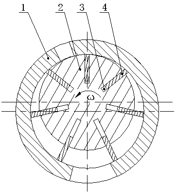
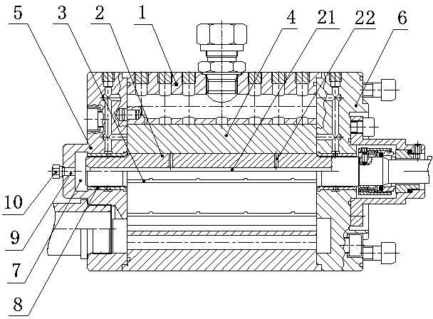
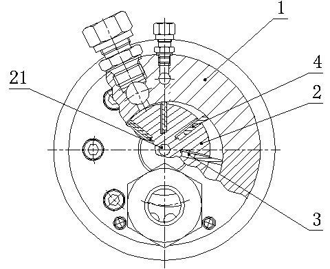
[0023] Such as figure 2 and image 3 As shown, the present invention includes a stator 1 containing a cylinder and a rotor 2 installed eccentrically in the stator cylinder. One side of the stator 1 is equipped with an exhaust end cover 5, and the other side of the stator 1 is equipped with an output shaft end cover 6. The inner side of the end cover 5 has a bearing positioning groove 7, and a bearing sleeve 8 is installed in the bearing positioning groove 7. One end of the rotor shaft is movably fitted on the bearing sleeve 8, and the other end of the rotor shaft protrudes from the output shaft end cover 6 to output power. The slot 3 is equipped with a sliding piece 4 that slides radially, the bearing positioning groove 7 of the exhaust end cover 5 is provided with a fluid through hole 9, and the end face of the rotor shaft located in the bearing positionin...


PUM


Abstract

The invention discloses a slip sheet expander. The slip sheet expander comprises a stator comprising an air cylinder and a rotor which is eccentrically mounted inside the air cylinder of the stator, wherein an exhaust end cover is arranged on one side of the stator, and an output shaft end cover is mounted on the other side of the stator; a bearing positioning groove is formed in the inner side of the exhaust end cover; a bearing sleeve is mounted inside the bearing positioning groove; one end of a rotor shaft movably sleeves the bearing sleeve, and the other end of the rotor shaft extends out of the output shaft end cover so as to output power; slip sheets sliding in the radial direction are mounted inside rotor grooves; a fluid through hole is formed in the bearing positioning groove of the exhaust end cover; a fluid passage is formed in a rotor shaft end face positioned inside the bearing positioning groove in the axial direction; one or more branch passages are formed in the bottom of each rotor groove in the radial direction; the branch passages are communicated with the fluid passage. The slip sheet expander has the advantages that the slip sheets are controlled by a high pressure fluid under the condition that the rotor is free of initial speed and can automatically stretch out of the rotor grooves at the right moment, so that normal startup of the slip sheet expander is realized, the slip sheet expander is reliable to use, and miniaturization is realized.

Description

technical field [0001] The invention belongs to a mechanical device for realizing energy conversion by using a fluid medium, in particular to a sliding vane expander. Background technique [0002] An expander is a device that converts the pressure energy contained in high-pressure gas, liquid or gas-liquid mixture into mechanical energy. [0003] The structure of the sliding vane expander is as follows figure 1 As shown, it has a stator 1 including a cylinder, a rotor 2 is installed in the stator cylinder, the axis of the rotor 2 deviates from the axis of the stator cylinder, and a plurality of axial rotor slots 3 are opened on the outer circumference of the rotor 2, and the rotor slot 3 A slide plate 4 that slides radially is placed inside. Due to the eccentric configuration of the rotor in the cylinder, the space volume formed by the inner wall of the cylinder and the outer surface of the rotor is asymmetrical, and the space volume of one arc section is narrow while that...

Claims


Application Information

Patent Timeline
06 Aug 2014
Publication
CN103967529A
IPC
F01C1/344; F01C21/18
Inventors
巫山; 黄少飞