Pedaling Torque Sensor Device for Each Cyclist's Leg and Power Meter Apparatus

a technology of pedals and sensors, applied in the direction of torque measurement, electric digital data processing, instruments, etc., can solve the problems of losing important information about the biomechanics of cycling, complex measurement system based on pedals, and inability to accurately measure the torque, etc., to avoid bulkiness, excess weight and volume of other setting-up, and maintain the weight and mechanical rigidity of crank arms suitable for use. , the effect of high accuracy in measuremen

Inactive Publication Date: 2014-07-17
CARRASCO VERGARA PABLO
View PDF1 Cites 19 Cited by
  • Summary
  • Abstract
  • Description
  • Claims
  • Application Information

AI Technical Summary

Benefits of technology

[0014]To function, this instrumented crank arm is necessarily connected to an electronic module whose mission is to transform the strain gauges deformation, reproducing local deformation, into electrical signal. Due to the symmetrical disposition of the gauges in this instrumented crank arm, and once electrically connected in opposed configuration, it is achieved that only in the case of measurements of opposite deformations will result in an output signal. So this configuration of the gauges only responds to deflections of the crank in the working direction of the crank arm, i.e. orthogonal to the longitudinal axis of the crank arm and included in the plane of symmetry, giving null values for all the other crank efforts: traction-compression, torsion (along its longitudinal axis) and lateral deflection (normal to the plane of symmetry), obtaining directly from the electronic module a linear output signal which is proportional to the value of the crank bending moment according to its working direction. And inasmuch as this direction is, for the geometric nature of the crank arms, practically coincident with the bottom bracket axis, the bending moment measured by the sensor according to the invention accurately approximates the torque exerted by the cyclist's leg in the bottom bracket axis.
[0015]This eliminates the need of electronic corrections or computer programming which have some of the torque measuring systems included in the Prior Art, to transform the data collected by the corresponding sensors, because in the case of the present invention said deflection value is obtained without further conversion than the necessary homothety to change the measured data units following a previous calibration process for this pedaling torque sensor device.
[0016]Technical problems existing in the Prior Art that solves the pedaling torque sensor device according to the invention derive from this geometric configuration and are both structural and functional. Structurally because in order to house the gauges, it is based in a conventional crank arm, in use and proportions, thus keeping the weight and the mechanical rigidity of a crank arm suitable for use even in professional cycling, road and MTB (mountain bike); in addition, it gives total protection against external elements to the area equipped with gauges, avoiding therefore the bulkiness, excess weight and volume of other setting-up. On the other hand, functionally it achieves a direct ratio between the input and the output, i.e. between torque and electric signal, which helps to have a high accuracy in the measurement while a lower electric power consumption in the batteries needed for operation.
[0019]This not only makes it possible to calculate and display the percentage data for the power balance distributed between both legs, called BALANCE LEFT-RIGHT; but it also makes it possible to calculate and display the ratio between power delivered during the pedaling downstroke and power delivered during the rising phase of the pedal for each leg, called BALANCE PUSH-PULL, furthermore calculating this ratio for each leg and / or for both overall.

Problems solved by technology

However, based on the total power produced by the cyclist, you lose important information about the biomechanics of cycling, as it is important to know how you are working with each leg and the way this work is; for example the way you pedal during the rising phase of your legs, or how uniform is the applied force.
In addition, individualized torque and power measurement systems per leg have been based on the instrumentation of the pedals, the crank arms or even fitting in the cyclist's shoes insoles with pressure sensors, the latter being very inaccurate when trying to know the effective force applied to each pedal.
Considering these systems have not yet reached the market after the time elapsed since they were respectively announced, it makes sense to imagine how complex measurement system based on the pedals are, especially considering that many of the forces applied on the pedals are not generating torque and therefore do not generate power.
For these reasons, plus the complexity added to such small space, and its sensitive location as exposed to potential impacts, we consider that the measurement systems on the pedals are not appropriate for a product capable of reaching the market and achieve reliable measurements with a solid product.
So far, the problem of these systems is the bulkiness or simply the exposure to hits and scrapes and in addition, the added complexity in the electronics necessary to obtain the torque from local deformation data measured by multiple gauges.

Method used


Image

  • Pedaling Torque Sensor Device for Each Cyclist's Leg and Power Meter Apparatus
  • Pedaling Torque Sensor Device for Each Cyclist's Leg and Power Meter Apparatus
  • Pedaling Torque Sensor Device for Each Cyclist's Leg and Power Meter Apparatus

Examples


Embodiment Construction

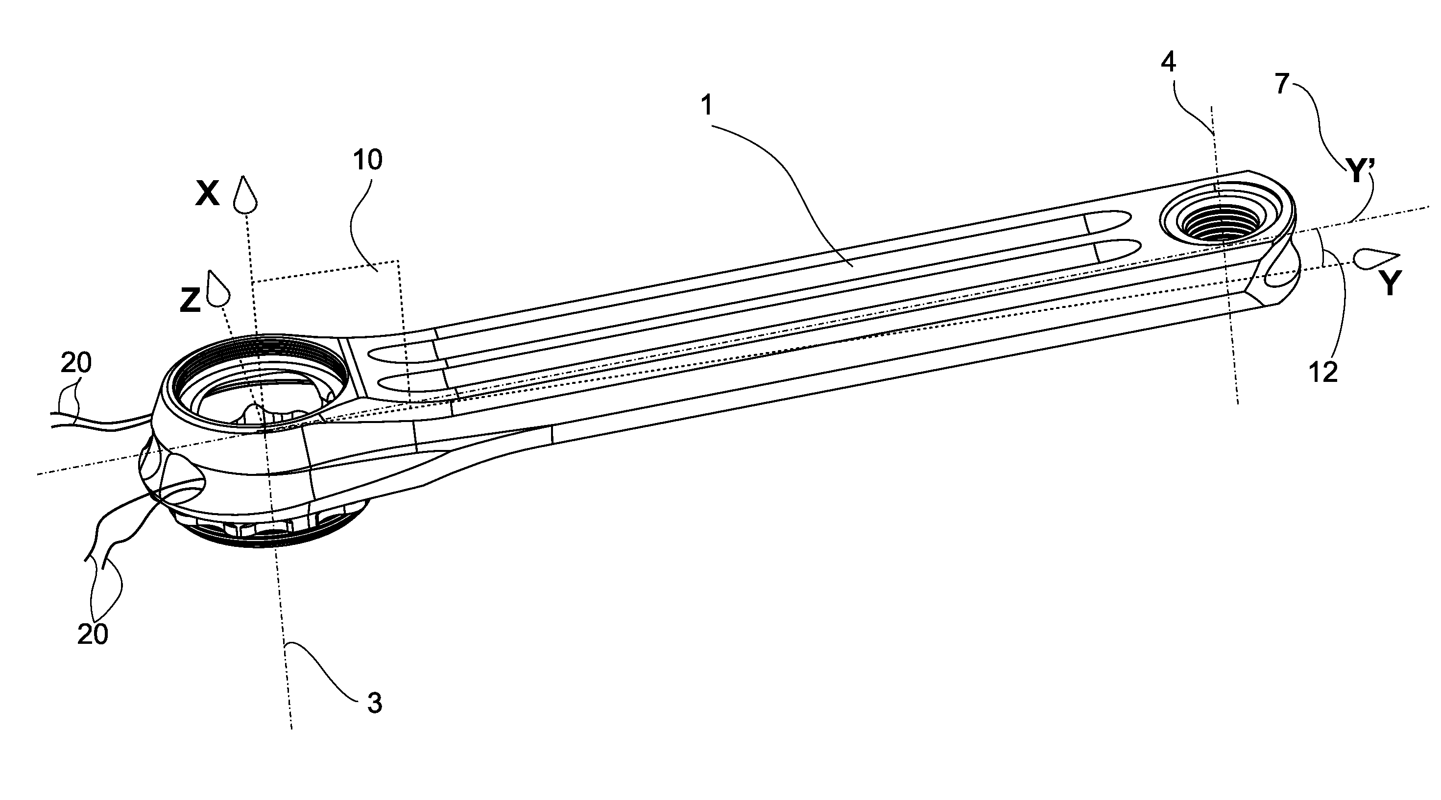
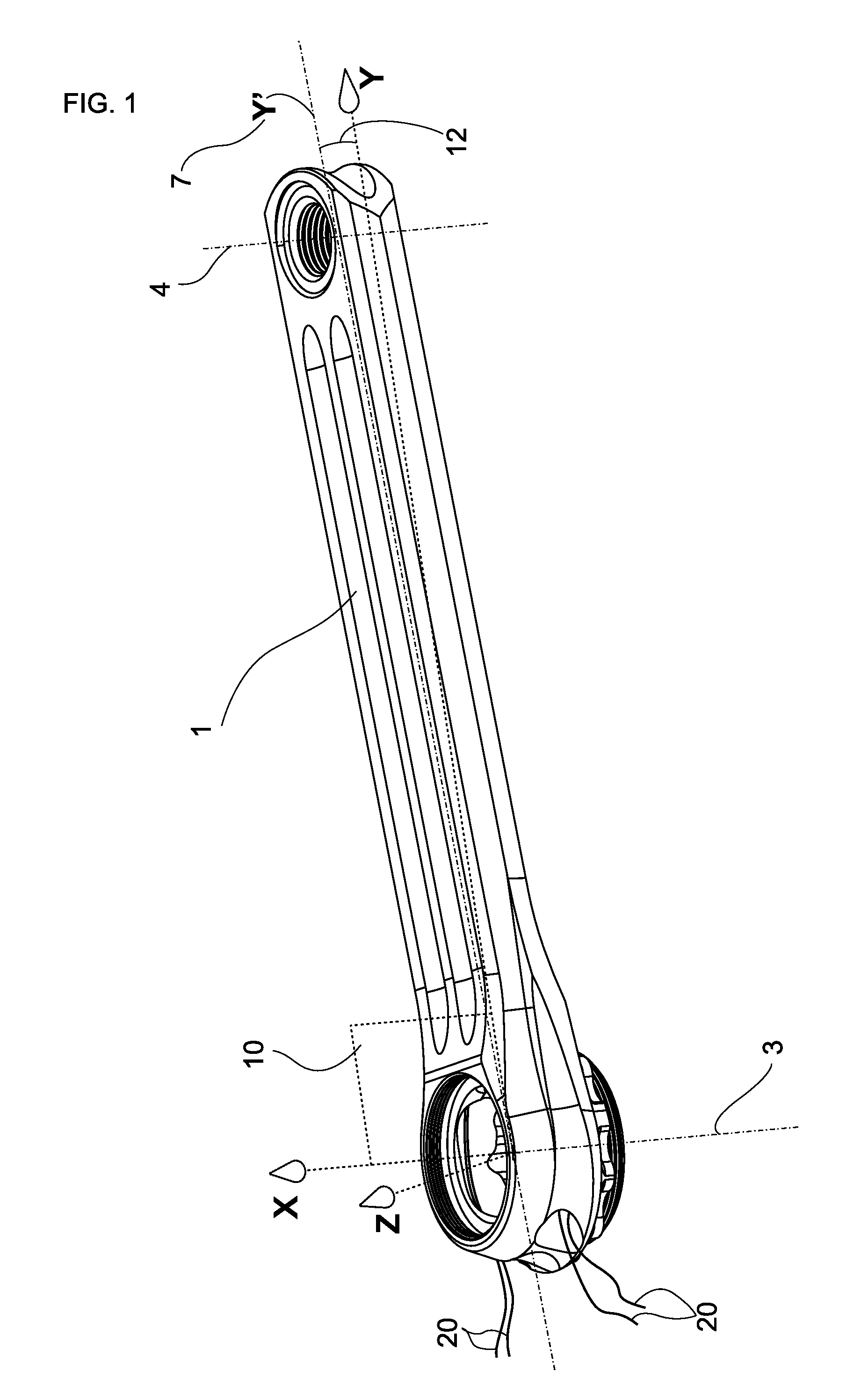
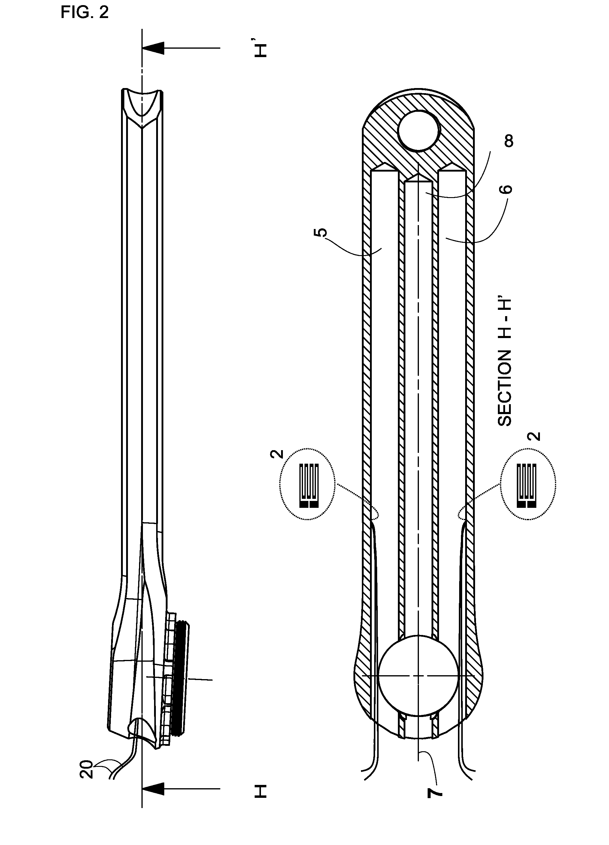
[0028]A crank arm (1) is proposed which, in addition to its structural function of converting the forces exerted on the pedal coupled thereto in torque around the bottom bracket, becomes a sensor of said torque once it has been instrumented. This pedaling torque sensor device consists therefore in a special construction crank arm equipped internally with strain gauges (2), which are connected to a corresponding electronic module (30) to know its deflection in the pedaling plane and therefore directly the torque applied by each one of the cyclist's legs. In addition, we propose a power meter apparatus (40) comprising two aforementioned pedaling torque sensor devices

[0029]This pedaling torque sensor device for bicycles to measure the torque exerted in the direction of a bottom bracket axle by one cyclist's leg when operates a pedal, comprises a bicycle crank arm (1) performed in a tubular straight single-piece element, which connects said pedal with said bottom bracket, having a plane...


PUM

PropertyMeasurementUnit
opening angleaaaaaaaaaa
symmetryaaaaaaaaaa
angular velocityaaaaaaaaaa

Abstract

Pedaling torque sensor device for bicycles comprising a crank arm (1) performed in a single-piece element having a cross section closed and symmetrical about a plane of symmetry (10) and also symmetric about the plane which is orthogonal to said plane (10) containing the main longitudinal axis of the crank arm (7). Said crank arm (1) is provided with at least one couple of straight drilled blind holes (5, 6) respectively symmetric about the mentioned plane of symmetry (10), and each one of the mentioned strain gauges (2) are non-detachably fixed on the inside of the crank arm (1) within 10 the straight drilled blind hole (5, 6) walls.It is also object of the invention a power meter apparatus (40) to calculate jointly and separately the instantaneous power delivered for each cyclist's leg, comprising two of the aforementioned pedaling torque sensor devices, means to measure the instantaneous angular velocity of the crankset and a power meter CPU (35) that integrates and processes the signals received.

Description

[0001]In the field of bicycles, the present invention relates to a measuring device for the torque and the power that a cyclist generates with each single leg when pedaling, which helps to analyze the involvement of different groups of muscles and the possible asymmetries between the two legs, not only in the laboratory but also as a standalone on one's bike, improving the quality of training and sports performance.PRIOR ART[0002]There are several systems measuring either forces or applied torque by the cyclist, and therefore are also able to measure the power when the speed or the corresponding angular velocity is known.[0003]Systems being implemented on cycling obtain the data torque, often based on the use of strain gauges, by measuring the elastic deformation in some of the drivetrain system components caused by mechanical loads introduced by the cyclist pedaling. The torque calculated in the bottom bracket spindle multiplied by the crankset rotational speed is the instantaneous...

Claims


Application Information

Patent Timeline
Patent Type & Authority Applications(United States)
IPC IPC(8): G01L3/10
CPCG01L3/10G01L3/00
Inventor CARRASCO VERGARA, PABLO
Owner CARRASCO VERGARA PABLO
Why Eureka
Try Eureka