Backlight module and liquid crystal display
A backlight module and liquid crystal display technology, applied in the direction of instruments, optics, light guide, etc., can solve the problems of expansion and contraction deformation, easy damage of materials, high price of light guide plate and optical film, etc., to improve utilization rate, reduce Small thickness, the effect of improving quality
- Summary
- Abstract
- Description
- Claims
- Application Information
AI Technical Summary
Problems solved by technology
Method used
Image
Examples
Embodiment 1
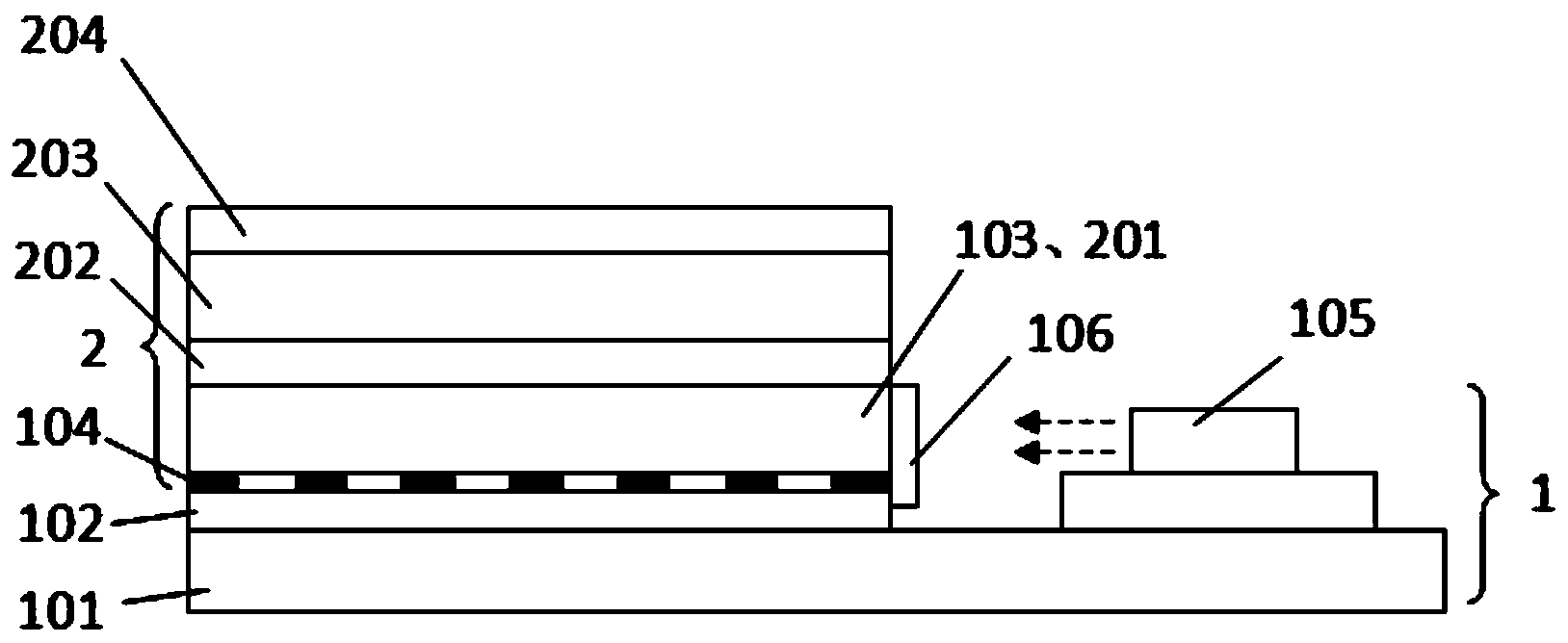
[0031] figure 2 A schematic structural diagram of the backlight module and the liquid crystal display provided in this embodiment. Such as figure 2 As shown, the liquid crystal display includes a liquid crystal display 2 and a backlight module 1, wherein the liquid crystal display 2 at least includes a TFT glass substrate 201, a liquid crystal layer 202, a CF glass substrate 203 and a second polarizer 204 that are sequentially stacked. The optical module 1 comprises a backplane 101, a reflection sheet 102 positioned on the backplane 101, a glass substrate 103 positioned on the reflection sheet 102 (the TFT glass substrate 201 in the liquid crystal display 2 is the same part) and The backlight 105 is disposed on the side of the glass substrate 103 . Wherein, the side of the glass substrate 103 facing the reflection sheet 102 is provided with an optical network dot structure layer 104 , and the other side of the glass substrate 103 is a light-emitting surface (with an FTF ar...
Embodiment 2
[0036] image 3 A schematic structural diagram of the backlight module and the liquid crystal display provided in this embodiment. Such as image 3 As shown, the difference from Embodiment 1 is that the first polarizer 106 in this embodiment is fixed at a distance from the side of the glass substrate 103 by a fastener 107 . The position only needs to be between the glass substrate 103 and the backlight 105 . The purpose of disposing the first polarizer 106 at a certain distance from the side of the glass substrate 103 is for easy fixing and better stability. The structure of the liquid crystal display 2 of the liquid crystal display and other structures in the backlight module 1 are the same as those in the first embodiment.
Embodiment 3
[0038] Figure 4 A schematic structural diagram of the backlight module and the liquid crystal display provided in this embodiment. Such as Figure 4 As shown, the difference from Embodiment 2 is that an optical film set 108 is also arranged between the first polarizer 106 and the backlight source 105 in this embodiment (in other embodiments, the optical film set 108 is also It may be arranged between the first polarizer 106 and the glass substrate 103). Wherein, the optical film group 108 may be selected from one or more arbitrary combinations of a diffusion film, a prism film and an anti-reflection film. The structure of the liquid crystal display 2 of the liquid crystal display and other structures in the backlight module 1 are the same as those in the second embodiment.
[0039] In this embodiment, the optical film group 108 is arranged between the first polarizer 106 and the backlight source 105, which improves the quality of the light emitted by the backlight source 105...
PUM
 Abstract
Description
Claims
Application Information
 - R&D
- Intellectual Property
- Life Sciences
- Materials
- Tech Scout
- Unparalleled Data Quality
- Higher Quality Content
- 60% Fewer Hallucinations
Browse by: Latest US Patents, China's latest patents, Technical Efficacy Thesaurus, Application Domain, Technology Topic, Popular Technical Reports.
© 2025 PatSnap. All rights reserved.Legal|Privacy policy|Modern Slavery Act Transparency Statement|Sitemap|About US| Contact US: help@patsnap.com


