Air tube heat exchanger

A heat exchanger and air duct technology, which is applied in the field of air conditioning and heat exchange devices, can solve the problems of small diameter of the sealed pipe of the fin heat exchanger, narrow gap between fins and increased installation and construction difficulty, etc. Achieve the effect of increasing heat exchange area and time, high heat exchange rate and reducing power

Inactive Publication Date: 2014-08-06
威海瑞冬空调有限公司
View PDF0 Cites 0 Cited by
  • Summary
  • Abstract
  • Description
  • Claims
  • Application Information

AI Technical Summary

Problems solved by technology

The characteristics of the finned heat exchanger are: First, the finned heat exchanger is composed of a sealed pipe and fins attached to the outside of the pipe, and the cold / heat of the cold / heat medium is transferred to the air through the pipe and the fins. Indoor / outdoor air changes the temperature and humidity of the air; the second is that the diameter of the sealed tube of the fin heat exchanger is relatively small, and the gap between the fins is relatively narrow, so that the cold / heat medium passing through the tube and the fins The air flow passing between the fins is less, so the heat transfer effect is limited; in addition, because the air flow passing between the fins is hindered by the fins, it is necessary to use fan equipment to pressurize the air in an orderly manner to make it flow quickly , which increases energy consumption; third, during the installation and use of fin heat exchange equipment, since the pipeline of the fin heat exchanger is small and easy to collect gas, the pipeline must have a certain slope when installing, and The requirements are relatively strict, which increases the difficulty of installation and construction; during use, due to the small size of the pipeline of the fin heat exchanger, blockage and unsmooth conditions occur from time to time, so after a period of operation, the system needs to be cleaned

Method used


Image

  • Air tube heat exchanger
  • Air tube heat exchanger

Examples


Embodiment Construction

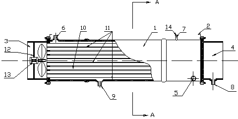
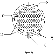
[0015] From Figure 1-2 It can be seen from the figure that an air duct heat exchanger includes a shell 1 and a mounting bracket 2 provided on the shell 1, and is characterized in that: the shell 1 is in the shape of a barrel, and the two ends of the shell 1 are open , one end of the housing 1 is an air inlet 3, the other end of the housing 1 is an air outlet 4, and the housing 1 is provided with a liquid inlet 5, a liquid outlet 6, an exhaust port 7, a drain port 8 and a sewage outlet 9. There are several round tubes 10 inside the shell 1, the two ends of the round tubes 10 are open, and the closed liquid cavity 11 is between the two ends of the round tubes 10, and the air inlet 3 of the shell 1 is provided with a filter 12 and fan 13. The liquid inlet 5 and the liquid outlet 6 are connected with the host through pipelines. Valves 14 are provided on the exhaust port 7 and the sewage discharge port 8 . The drain port 8 is connected to the drain pipe. The fan 13 power suppl...


PUM


Abstract

An air tube heat exchanger comprises an outer shell and an installation frame arranged on the outer shell. The air tube heat exchanger is characterized in that the outer shell is in a barrel shape. The two ends of the outer shell are open, an air inlet is formed in one end of the outer shell, and an air outlet is formed in the other end of the outer shell. A liquid inlet, a liquid outlet, an exhaust port, a drainage outlet and a sewage draining outlet are formed in the outer shell. Multiple round tubes are arranged in the outer shell, the two ends of each round tube are open, and a closed liquid cavity is formed between the two ends of each round tube. A filter net and a fan are arranged in the air inlet of the outer shell. The liquid inlet and the liquid outlet are in linkage with a main engine through pipelines. A valve is arranged on the exhaust port. The drainage outlet is connected with a drainage pipe. A power source of the fan is in linkage with the main engine.

Description

technical field [0001] The invention relates to an air conditioning and heat exchange device, in particular to an air pipe heat exchanger. Background technique [0002] At present, the known heat conduction forms in the field of air conditioning mainly include shell-and-tube type, fin type and plate type. The shell-and-tube type and the plate type are completed through the conduction between two liquids, and these two forms of heat conduction are applied to the refrigeration / heater part of the entire air conditioning system. Fin heat exchange can be applied to refrigeration / heating machines or to the end of air-conditioning systems, and is widely used. The characteristics of the finned heat exchanger are: First, the finned heat exchanger is composed of a sealed pipe and fins attached to the outside of the pipe, and the cold / heat of the cold / heat medium is transferred to the air through the pipe and the fins. Indoor / outdoor air changes the temperature and humidity of the ai...

Claims


Application Information

Patent Timeline
Patent Type & Authority Applications(China)
IPC IPC(8): F25B39/00F24F13/30
Inventor 姜天华吴建国
Owner 威海瑞冬空调有限公司
Why Eureka
Try Eureka