Lamp discharge time test circuit

A discharge time and test circuit technology, applied in the field of lamp discharge time test circuit, can solve the problems of large recording error and labor consumption, and achieve the effect of simple circuit structure

Inactive Publication Date: 2016-09-07
OCEANKING DONGGUAN LIGHTING TECH +2
View PDF5 Cites 0 Cited by
  • Summary
  • Abstract
  • Description
  • Claims
  • Application Information

AI Technical Summary

Problems solved by technology

At present, most of the lighting manufacturers in the industry rely on manual recording of the discharge time, which leads to the test of the discharge time of the lamps, which is not only labor-intensive but also has a large recording error.

Method used


Image

  • Lamp discharge time test circuit
  • Lamp discharge time test circuit
  • Lamp discharge time test circuit

Examples


Embodiment Construction

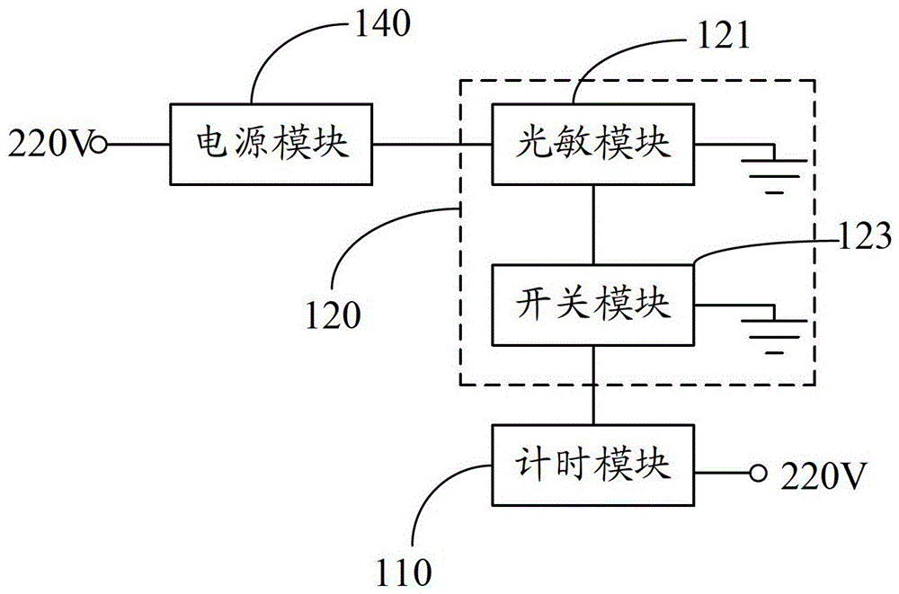
[0025] Such as figure 1 Shown is the module diagram of the lamp amplification time test circuit.

[0026] A lamp discharge time testing circuit for recording the discharge time of lamps, comprising a timing module 110 for recording the discharge time of lamps and a photosensitive control module 120 for controlling the timing state of the timing module 110 .

[0027] The photosensitive control module 120 is connected with the timing module 110, and controls the timing module 110 to start timing when it senses the lighting of the lamp; it controls the timing module 110 to stop timing when it does not sense the lighting of the lamp.

[0028] The photosensitive control module 120 includes a photosensitive module 121 for sensing the lighting state of the lamp and a switch module 123 for controlling the timing module 110 to be turned on or off. electrical connection.

[0029] When the photosensitive module 121 senses the discharge of the lamp, the photosensitive module 121 is turn...


PUM


Abstract

A test circuit for discharge time of a lamp is used for recording the discharge time of the lamp and comprises a timing module and a photosensitive control module. The timing module is used for recording the discharge time of the lamp. The photosensitive control module is used for controlling timing state of the timing module and connected with the timing module. If the photosensitive control module senses the lamp discharging, the timing module is controlled to start to time by the same; if not, the timing module is controlled to stop timing by the same. The test circuit for the discharge time of the lamp adopts the photosensitive control module to sense the discharge state of the lamp. When the lamp is in discharging, the photosensitive control module is conducted; when the lamp stops discharging, the photosensitive control module is cut-off. The timing module is connected with the photosensitive control module and controlled by the conducting state of the same. when the photosensitive control module is conducted, the timing module starts to time; when the photosensitive control module is cut-off, the timing module stops timing. Thus, the accurate discharge time of the lamp is recorded by adopting the test circuit with simple structure.

Description

technical field [0001] The invention relates to a lamp test circuit, in particular to a simple and accurate lamp discharge time test circuit. Background technique [0002] With the development of the lighting industry, the discharge time of mobile and portable lamps is usually calculated based on theoretical load power and battery capacity. If it is necessary to obtain the accurate value of the discharge time of the lamp, the actual charge and discharge records are generally made by experimental methods. At present, most of the lighting manufacturers in the industry rely on manual recording of the discharge time, which leads to the test of the discharge time of the lamps, which is not only labor-intensive but also has a large recording error. Contents of the invention [0003] Based on this, a simple and accurate recording lamp discharge time test circuit is provided. [0004] A lamp discharge time test circuit for recording the discharge time of lamps, including a timin...

Claims


Application Information

Patent Timeline
Patent Type & Authority Patents(China)
IPC IPC(8): G01R31/44G01R31/24
Inventor 周明杰陈钢
Owner OCEANKING DONGGUAN LIGHTING TECH
Why Eureka
Try Eureka