
Method for acquiring frequency response function of numerically-controlled machine tool based on cutting excitation

A technology of frequency response function and numerical control machine tool, applied in the direction of digital control, electrical program control, etc., can solve the problem that the frequency response function of the machine tool structure cannot be obtained directly

Active Publication Date: 2014-08-06
HUAZHONG UNIV OF SCI & TECH
View PDF5 Cites 7 Cited by
  • Summary
  • Abstract
  • Description
  • Claims
  • Application Information

AI Technical Summary

Problems solved by technology

[0004] The working modal analysis method developed in recent years only identifies the modal parameters of the machine tool structure by measuring the vibration response of the machine tool structure in the working state. However, in the actual working modal analysis, since the input force is unknown, it cannot Direct access to the frequency response function of the machine tool structure

Method used


Image

  • Method for acquiring frequency response function of numerically-controlled machine tool based on cutting excitation
  • Method for acquiring frequency response function of numerically-controlled machine tool based on cutting excitation
  • Method for acquiring frequency response function of numerically-controlled machine tool based on cutting excitation

Examples


Embodiment Construction

[0023] In this embodiment, the method of the present invention is preferably described by taking the XHK5140 vertical machining center as an example.

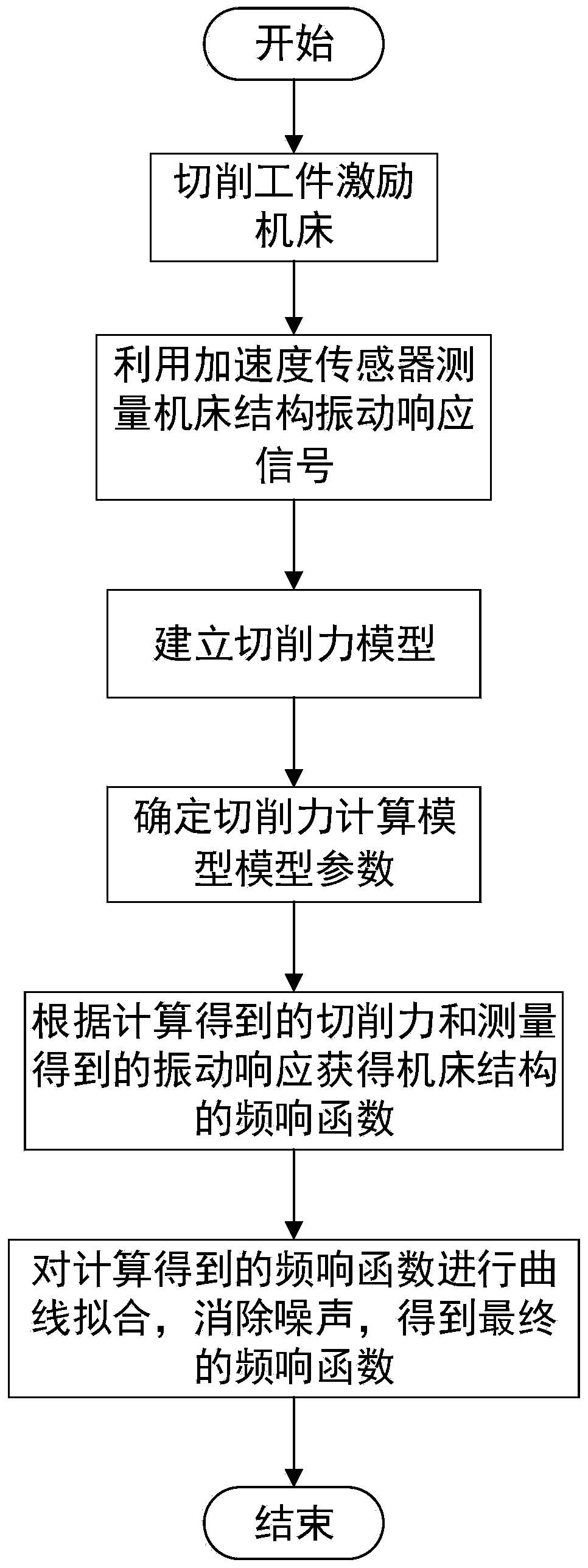
[0024] The method for synthesizing the frequency response function of the CNC machine tool under the working state of the present embodiment includes the following steps, wherein figure 1 Reflected the flow chart of frequency response function of the present invention:

[0025] (1) Obtain the vibration response output signal of the CNC machine tool in the cutting process

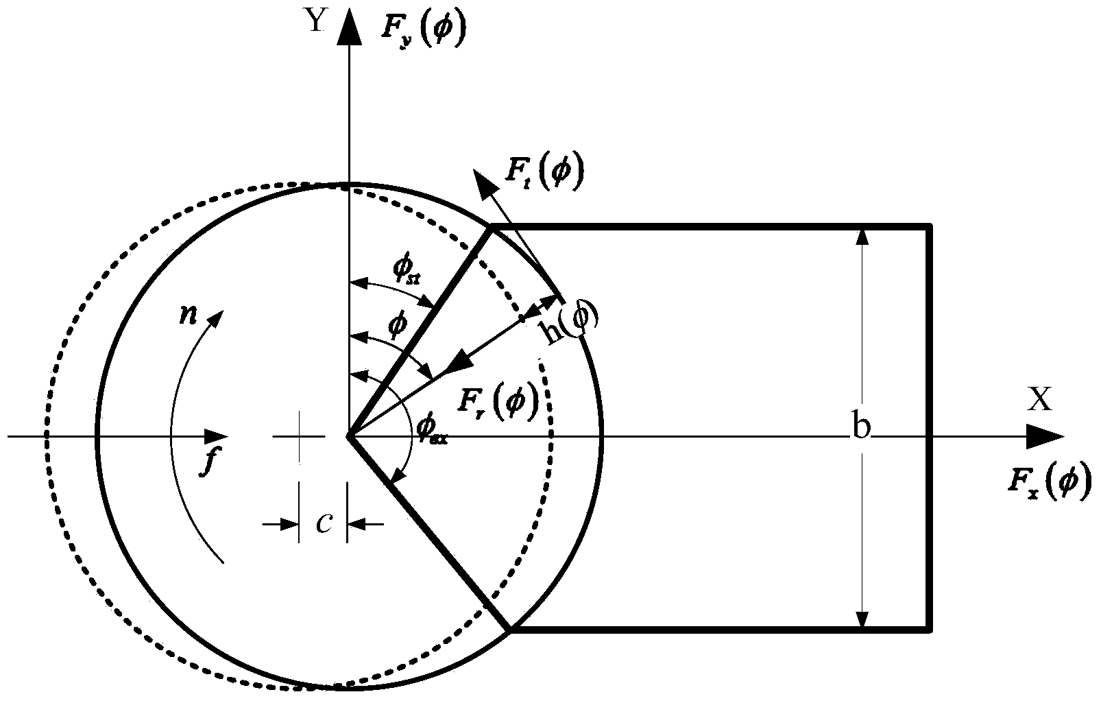
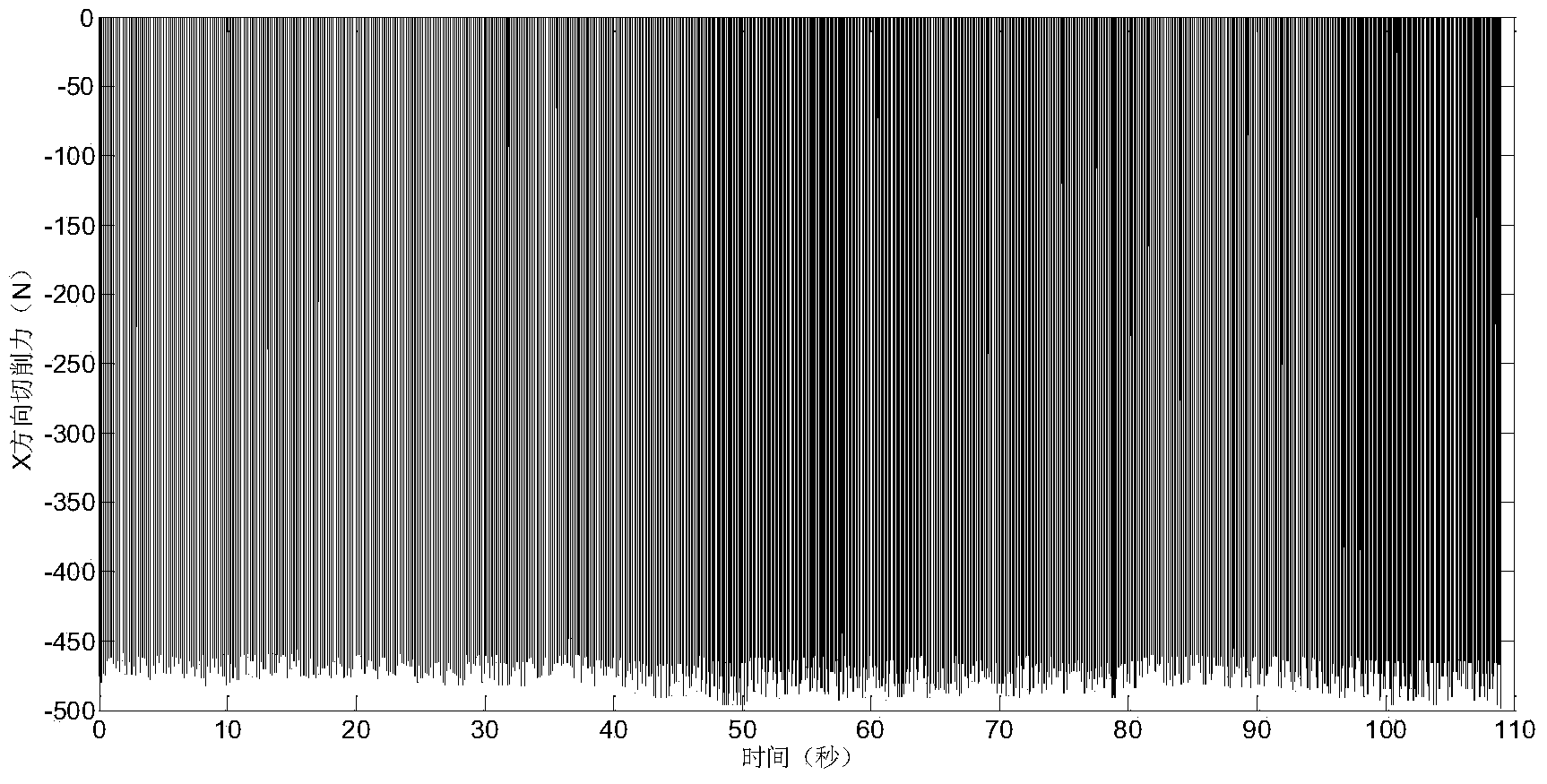
[0026] Choose an appropriate cutting excitation scheme, such as controlling the spindle to rotate randomly to cut workpieces, cutting workpieces with random shapes, etc., and excite the machine tool through the generated cutting force. In this embodiment, the machine tool is excited by controlling the main shaft to randomly rotate and cut the narrow boss workpiece; the acceleration sensor is used to measure the vibration response signal x(t) of key parts suc...


PUM


Abstract

The invention discloses a method for acquiring a frequency response function of a numerically-controlled machine tool based on cutting excitation. The method includes the steps that a machine tool structure is excited through random cutting force generated in a machine tool cutting project; vibration response signals of the position where the frequency response function needs to be acquired are measured through a sensor; a cutting force model is established, and the cutting force model is modified through a modification function according to the influence of the rotating speed change on the cutting force; coefficients in the cutting force calculation model are determined, and the modification function is fit according to experiments; the frequency response function of the machine tool structure is acquired according to the cutting force acquired through calculation and vibration response acquired through measurement, curve fitting is conducted on the frequency response function acquired through calculation, noise is eliminated, and then the final frequency response function is acquired. According to the method, dynamic characteristics of the machine tool with an accurate and reliable recognition result in an operating state can be acquired, and the optimization design of the machine tool structure and state monitoring of the machine tool can be conducted through the acquired frequency response function.

Description

technical field [0001] The invention belongs to the field of dynamic analysis of numerical control equipment structures, and in particular relates to a method for obtaining frequency response functions of numerical control machine tools based on cutting excitation. Background technique [0002] The dynamic characteristics of a machine tool are crucial to improving its machining performance and structural design. At present, the dynamic characteristics of the machine tool structure are mainly obtained based on the experimental modal analysis method of forced vibration. The main feature of this method is to apply a specific excitation force to the machine tool structure, and simultaneously measure the excitation force and the vibration response of the machine tool structure to obtain the frequency response function, and use the frequency response function to characterize the dynamic characteristics of the machine tool structure. [0003] However, the above method can only obt...

Claims


Application Information

Patent Timeline
IPC IPC(8): G05B19/18
Inventor 李斌毛新勇蔡辉闫睿智罗博张译寒刘响求潘大为彭芳瑜
Owner HUAZHONG UNIV OF SCI & TECH
Learn More