Motor device and motor speed control system

A motor and control device technology, applied in the direction of single motor speed/torque control, etc., can solve problems such as complex circuit structure, component cost, assembly man-hours, and device failure rate, and achieve the effect of simplifying circuit design

Active Publication Date: 2017-06-30
DELTA ELECTRONICS INC
View PDF3 Cites 0 Cited by
  • Summary
  • Abstract
  • Description
  • Claims
  • Application Information

AI Technical Summary

Problems solved by technology

Therefore, the overall circuit architecture is not only quite complex, but also has a negative impact on component cost, assembly man-hours, and device failure rates

Method used


Image

  • Motor device and motor speed control system
  • Motor device and motor speed control system
  • Motor device and motor speed control system

Examples


Embodiment Construction

[0025] A motor device and a motor speed control system according to preferred embodiments of the present invention will be described below with reference to related drawings, wherein the same components will be described with the same component symbols.

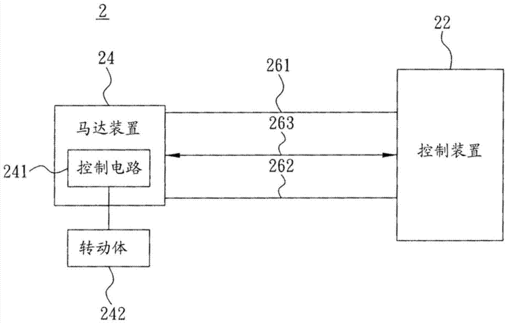
[0026] Please refer to figure 2 As shown, it is a schematic block diagram of a motor speed control system disclosed in the present invention. The motor speed control system 2 includes a control device 22, a motor device 24 and a positive coupling between the control device 22 and the motor device 24. A power signal line 261 , a negative power signal line 262 and a feedback / speed control signal line 263 . Therefore, the control device 22 controls the motor device 24, and further enables the motor device 24 to drive the action of the rotating body 242 connected thereto. At the same time, the motor device 24 also feeds back the rotation state of the rotating body 242 to the control device 22, so that the control device 22 can ...


PUM


Abstract

The present invention discloses a motor device and a motor speed control system, which utilizes two power signal lines and a feedback / speed control signal line to be coupled between the control device and the motor device, wherein the two power lines enable the control device and the motor device Electrically connected, and the feedback / speed control signal line bidirectionally transmits signals from the control device and the motor device.

Description

[0001] This application is a divisional application of the application with the application date of November 16, 2007 and the application number 200710186726.9 entitled "Motor Device and Motor Speed ​​Control System". technical field [0002] The invention relates to a motor device and a motor speed control system. Background technique [0003] A large number of signal lines with complex connections are usually coupled between the existing control motor device and the control device for controlling its rotation. For example, a common motor device (such as a brushless motor for driving a fan ) motor speed control system such as figure 1 As shown, the positive power signal line 161 and the negative power signal line 162 are coupled between the control device 12 and the motor device 14 so that the control device 12 and the motor device 14 are electrically connected to each other. In addition, the speed control signal line 163 connects the control device 12 The generated speed ...

Claims


Application Information

Patent Timeline
Patent Type & Authority Patents(China)
IPC IPC(8): H02P6/06
Inventor 邱进发
Owner DELTA ELECTRONICS INC
Why Eureka
Try Eureka