Semiconductor device
A semiconductor, conduction technology, applied in the direction of semiconductor devices, output power conversion devices, transistors, etc., can solve problems such as deviation, short circuit of power devices 12 and 13, etc.
- Summary
- Abstract
- Description
- Claims
- Application Information
AI Technical Summary
Problems solved by technology
Method used
Image
Examples
Embodiment 1
[0088] A-1. Device structure
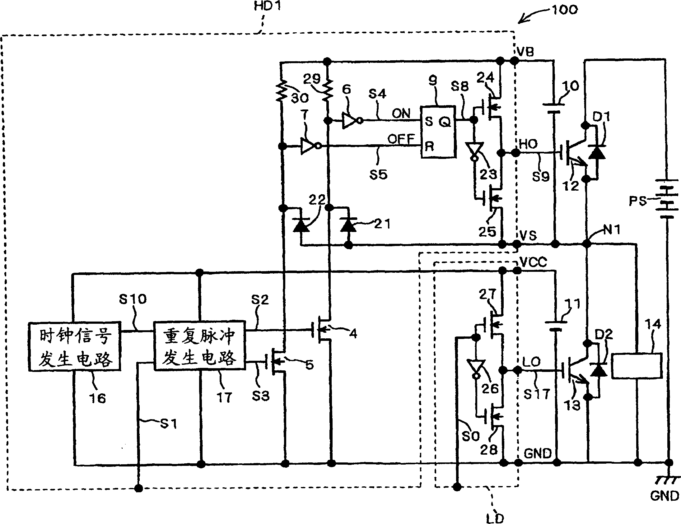
[0089] As Embodiment 1 of the semiconductor device of the present invention, figure 1 The structure of the level shift circuit 100 in the state mode is shown.
[0090] exist figure 1 Among them, power devices 12 and 13 such as IGBT (Insulated Gate Bipolar Transistor) are push-pull connected between the positive pole and the negative pole (ground potential GND) of the power supply PS to form a half-bridge power device. In addition, freewheeling diodes D1 and D2 are connected in parallel with power devices 12 and 13 in reverse direction, respectively. Furthermore, a load (inductive load such as a motor) 14 is connected to a connection point N1 between the power device 12 and the power device 13 .
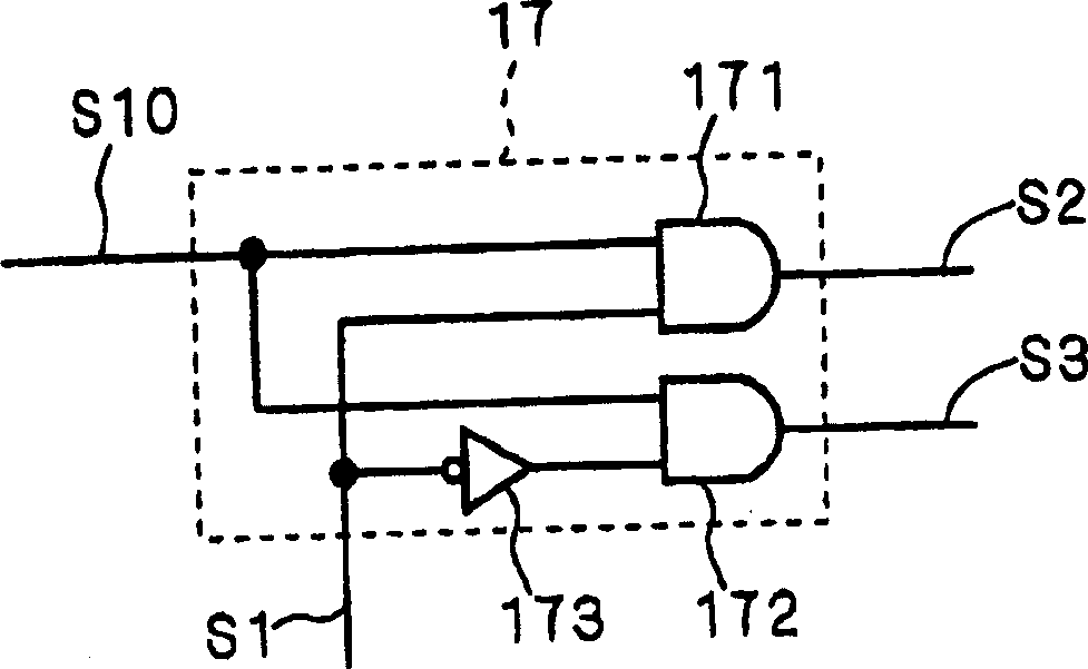
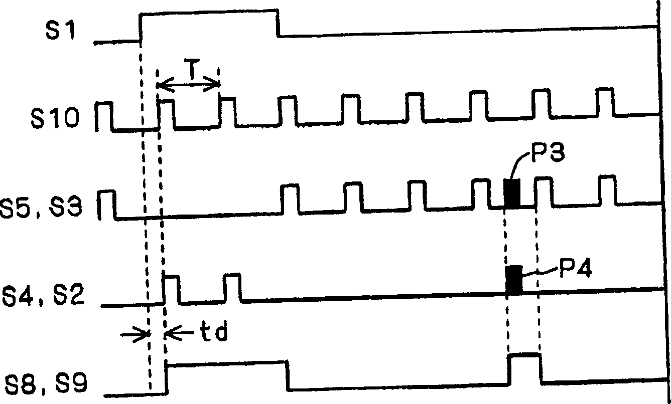
[0091] exist figure 1 Among them, the power device 12 uses the potential of the connection point N1 with the power device 13 as a reference potential, and switches between the reference potential and the power supply potential supplied by the powe...
Embodiment 2
[0123] B-1. Device structure
[0124] As Embodiment 2 of the semiconductor device of the present invention, Figure 4 The structure of the level shift circuit 200 is shown. exist Figure 4 in, for with figure 1 The same structures of the level shift circuit 100 shown are denoted by the same symbols, and repeated explanations are omitted.
[0125] Such as Figure 4 As shown, the level shift circuit 200 is divided into a high potential side power device drive circuit HD2 and a low potential side power device drive circuit LD. In the high potential side power device drive circuit HD2, there is no figure 1 The clock signal generation circuit 16 provided in the shown level shift circuit 100 supplies a clock signal supplied from the outside as a signal S10 to the repetitive pulse generation circuit 17 .
[0126] exist figure 1 In the shown level shift circuit 100, the pulse signal generated by the own clock signal generation circuit 16 is used. However, at this time, the ti...
Embodiment 3
[0137] C-1. Device structure
[0138] As Embodiment 3 of the semiconductor device of the present invention, Figure 6 The configuration of the level shift circuit 300 is shown. exist Figure 6 in, for and figure 1 The same structures of the level shift circuit 100 shown are denoted by the same symbols, and repeated explanations are omitted.
[0139] Such as Figure 6 As shown, the level shift circuit 300 is divided into a high potential side power device drive circuit HD3 and a low potential side power device drive circuit LD. In the high potential side power device drive circuit HD3, there is a level shifted OR circuit 19 that obtains a clock signal with the same frequency as the oscillation frequency of clock signal generating circuit 16 in the high potential area by logical sum of on-signal S4 of one bit and off-signal S5 that has been level-shifted.
[0140] That is, the outputs of the inverter circuits 6 and 7 are connected to the set input and reset input of the SR...
PUM
 Abstract
Description
Claims
Application Information
 - R&D
- Intellectual Property
- Life Sciences
- Materials
- Tech Scout
- Unparalleled Data Quality
- Higher Quality Content
- 60% Fewer Hallucinations
Browse by: Latest US Patents, China's latest patents, Technical Efficacy Thesaurus, Application Domain, Technology Topic, Popular Technical Reports.
© 2025 PatSnap. All rights reserved.Legal|Privacy policy|Modern Slavery Act Transparency Statement|Sitemap|About US| Contact US: help@patsnap.com


