Supercharge Your Innovation With Domain-Expert AI Agents!

Electrical Generator

A frequency converter and circuit technology, applied in the direction of circuit devices, control generators, AC network circuits, etc., can solve the problem of high cost and achieve the effect of cost saving

Inactive Publication Date: 2014-08-06
NIDEC CONTROL TECHN LTD
View PDF6 Cites 0 Cited by
  • Summary
  • Abstract
  • Description
  • Claims
  • Application Information

AI Technical Summary

Problems solved by technology

And modify the generator to have reactive power output capability, the cost will be too high

Method used


Image

  • Electrical Generator
  • Electrical Generator

Examples


Embodiment Construction

[0029] The following description of preferred embodiments is exemplary only and in no way restricts the invention and its application or usage. The same reference numerals are used to denote the same components in the respective drawings, and thus the configurations of the same components will not be described repeatedly.

[0030] The technical solutions of the present invention will be further described below in conjunction with the accompanying drawings and specific embodiments.

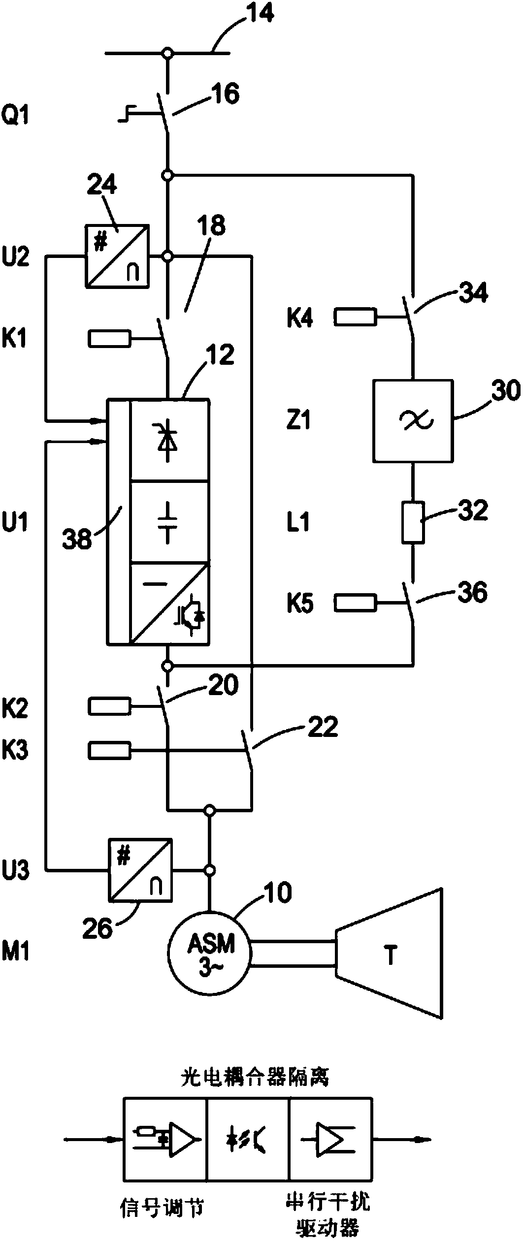
[0031] Such as figure 1 As shown, the power supply circuit of the asynchronous machine 10 is connected to the grid. In this embodiment, the power supply circuit includes a frequency converter 12 , and the frequency converter is a Unidrive SP frequency converter provided by Control Techniques Limited. The grid is represented by a horizontal line 14 , which is connected to the frequency converter 12 via a disconnect switch 16 and a mains switch 18 . The output end of the frequency converter 12 is ...


PUM


Abstract

An inverter circuit comprises an inverter which can be configurable for controlling the supply of mains current from a grid to an electric machine in a start-up mode whereby the machine drives the prime mover for initialisation. Thereafter the same inverter is reconfigurable as part of the circuit to supply reactive power to the grid when the machine is running as a generator powered by the prime mover.

Description

technical field [0001] The invention relates to the field of generators, in particular but not only to a generator using an asynchronous motor, and a frequency converter circuit for the motor. Background technique [0002] It is well known that when a generator is to be started to supply power to a grid or other network, the electric machines making up the generator can be run as engines, turning and accelerating the prime mover. To control the motor in such a motoring mode, a frequency converter is used to control the motor. The motor consumes electric power provided by the grid to drive the prime mover. In order to start the prime mover and accelerate. Once operating speed is reached, the motor can be configured as a generator driven by a prime mover and can supply power to the grid. Prime movers can be, but are not limited to, turbines and internal combustion engines of different types. [0003] Asynchronous motors, such as conventional squirrel-cage motors, are usual...

Claims


Application Information

Patent Timeline
IPC IPC(8): H02P27/04H02J3/18
CPCH02M7/42H02J3/1885H02P9/08Y02E40/30H02J3/1821H02J3/40
Inventor 彼得·艾根布罗特
Owner NIDEC CONTROL TECHN LTD
Features
  • R&D
  • Intellectual Property
  • Life Sciences
  • Materials
  • Tech Scout
  • Unparalleled Data Quality
  • Higher Quality Content
  • 60% Fewer Hallucinations
Learn More