Adjustable Duty Cycle Circuit

A duty cycle, adjustable technology, applied in the field of signal circuits, can solve problems such as inaccurate performance and degradation

Inactive Publication Date: 2014-08-06
QUALCOMM INC
View PDF7 Cites 0 Cited by
  • Summary
  • Abstract
  • Description
  • Claims
  • Application Information

AI Technical Summary

Problems solved by technology

Inaccuracies in the actual duty cycle can degrade the performance of any given application

Method used


Image

  • Adjustable Duty Cycle Circuit
  • Adjustable Duty Cycle Circuit
  • Adjustable Duty Cycle Circuit

Examples


Embodiment Construction

[0023] In accordance with the present disclosure, techniques for adjusting the pulse width and / or duty cycle of a signal generated by a circuit are disclosed.

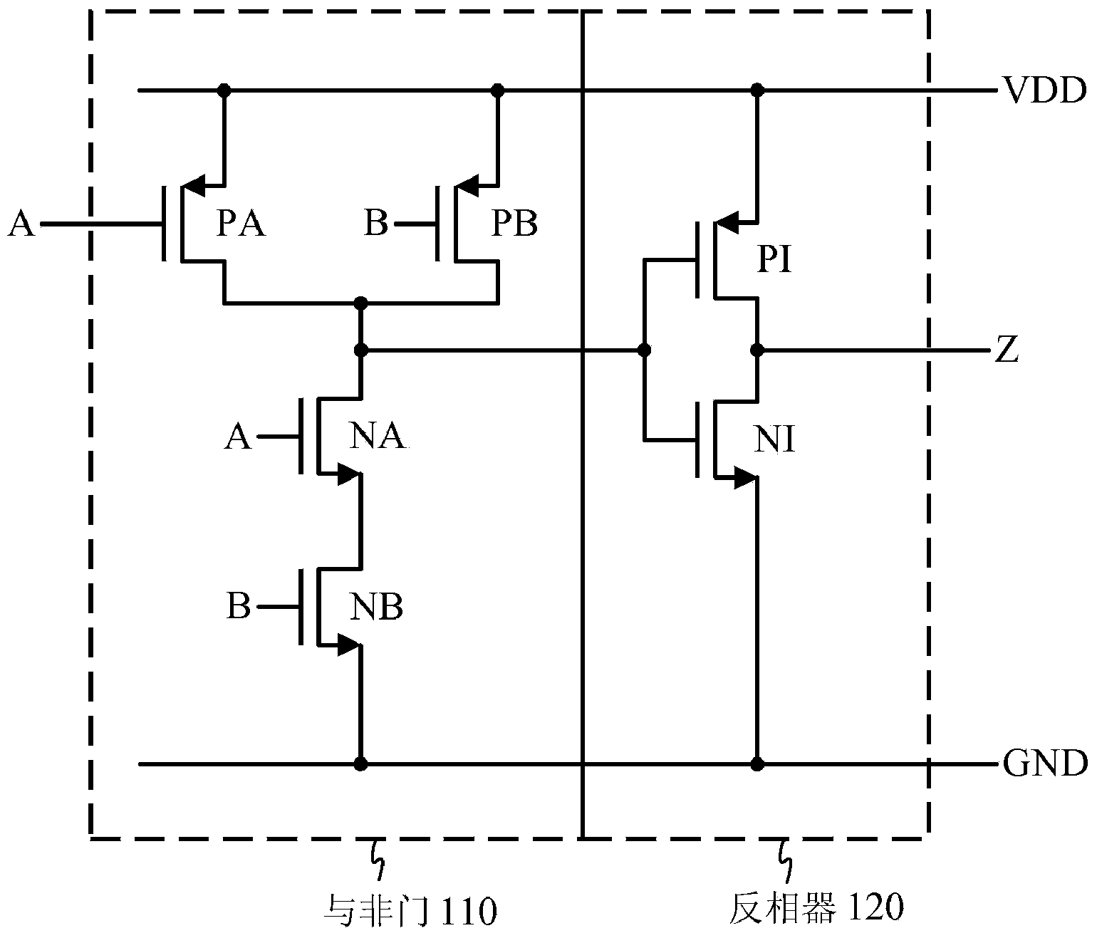
[0024] figure 1 Depicted is a circuit for generating a signal with a 25% duty cycle from an in-phase signal (A) and a quadrature-phase signal (B), each having a 50% duty cycle. exist figure 1 , PMOS transistors PA, PB and NMOS transistors NA, NB are configured as a standard two-input NAND gate 110 . Signal A and signal B are input to the NAND gate, and the output of the NAND gate is coupled to an inverter 120 to generate an output signal Z. Signal Z corresponds to the output of applying an "AND" operation to signal A and signal B.

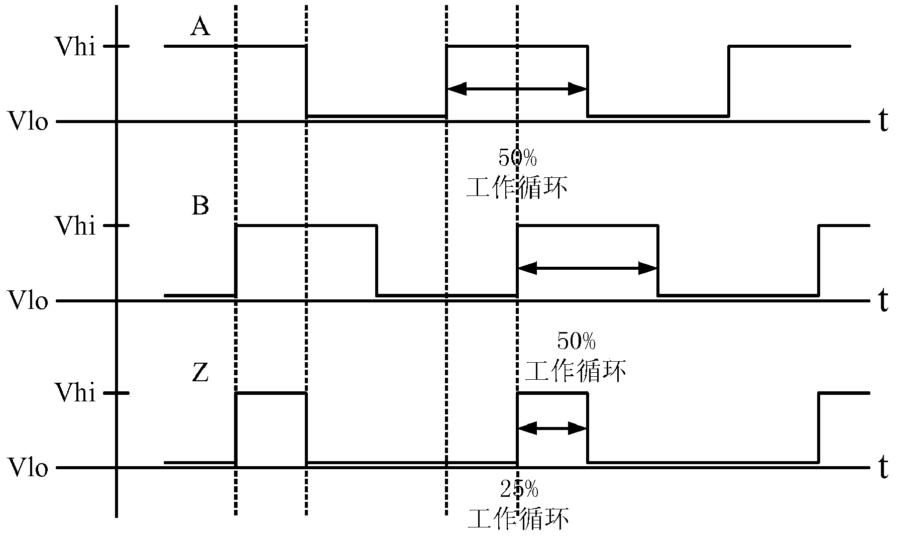
[0025] figure 2 Plot the relationship between Signal A, Signal B, and Signal Z. exist figure 2 , Signal A and Signal B each have a 50% duty cycle and have a quadrature phase relationship with each other. Signal Z, produced by applying an "AND" operation to signal A and signal B, ...


PUM


Abstract

Techniques are disclosed for adjusting and programming the duty cycle of a signal generated by a circuit. In an embodiment, parallel transistors are coupled between a NAND gate and a supply voltage. Selectively enabling the parallel transistors adjusts the switching point of the NAND gate, thereby allowing control of the pulse width of the output signal. In an alternative embodiment, the size of the PMOS versus the NMOS transistors in the NAND gate is selectively varied to achieve the same effect. Further disclosed are applications of the techniques to calibrating the receiver to minimize measured second-order inter-modulation products and / or residual sideband.

Description

[0001] Information about divisional applications [0002] This application is a divisional application of the original Chinese invention patent application titled "Adjustable Duty Cycle Circuit". The application number of the original application is 200880114749.1; the application date of the original application is November 9, 2008; the priority date of the original invention patent application is November 8, 2007. [0003] priority [0004] This application claims the benefit of U.S. Provisional Application No. 60 / 986,397, filed November 8, 2007, entitled "ADJUSTABLEDUTY CYCLE CIRCUIT," the entire disclosure of which is deemed to be the subject of this application. part of the disclosure of the application. technical field [0005] This invention relates to electronic circuits, and more particularly to circuits for generating signals with adjustable duty cycles. Background technique [0006] In the field of electronic circuit design, certain applications require the ...

Claims


Application Information

Patent Timeline
Patent Type & Authority Applications(China)
IPC IPC(8): H03K3/017H03K5/156
CPCH03K5/1565H03K3/017H03K5/156
Inventor 弗雷德里克·博叙安东尼·弗兰西斯·塞戈里亚
Owner QUALCOMM INC
Why Eureka
Try Eureka