Supercharge Your Innovation With Domain-Expert AI Agents!

Insert for slot milling

一种嵌件、铣槽的技术,应用在铣刀、铣床设备、铣削切削刀片等方向,能够解决切削嵌件和铣刀破损、错误安装切削嵌件、不方便使用等问题,达到防止破损、提高加工质量、满足顾客需求的效果

Active Publication Date: 2014-08-06
KORLOY
View PDF7 Cites 1 Cited by
  • Summary
  • Abstract
  • Description
  • Claims
  • Application Information

AI Technical Summary

Problems solved by technology

[0013] However, the cutting insert 13 or 15 coupled to the insert mounting seat 11a of the milling cutter 1 formed with the circular mounting seat protruding member 11b is combined regardless of the positions of the insert mounting seats 11a on both sides, so it may be mistaken. The cutting insert is installed incorrectly, thus, the cutting insert and the milling cutter are broken and cause loss, and it is inconvenient to use

Method used


Image

  • Insert for slot milling
  • Insert for slot milling
  • Insert for slot milling

Examples


Embodiment Construction

[0034] Hereinafter, the rotary milling cutter of the present invention will be described in detail with reference to the drawings.

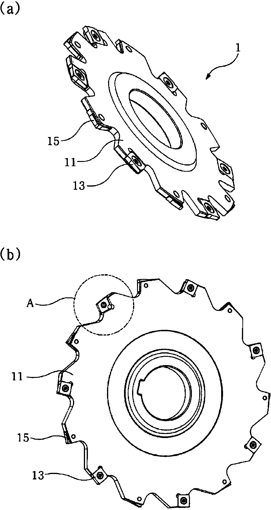
[0035] image 3 It is a schematic perspective view of the structure of the rotary milling cutter equipped with the insert of this invention.

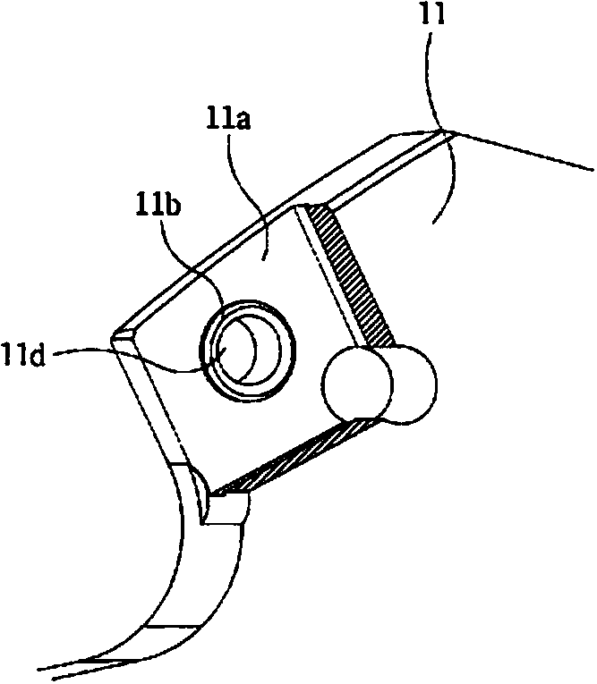
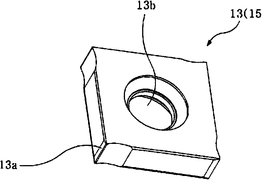
[0036] Figure 4 a to Figure 4 c is a schematic diagram for explaining the structure of the cutting insert according to the present invention and the state in which the cutting insert is coupled to the insert mounting seat of the milling cutter.

[0037] Figure 5 a and Figure 5 b is a schematic diagram of a case where the cutting insert of the present invention is correctly attached to the insert mounting seat of the milling cutter and a case where the cutting insert is incorrectly attached.

[0038] First, if Figure 3 to Figure 4 As shown in c, the cutting insert 50 of the present invention is installed on the cutting insert mounting seat 130 provided on the main body 110 of the milling cutter 1...


PUM


Abstract

The present invention relates to an insert for slot milling, and more specifically, to an insert for slot milling which can smoothly form a front end surface of a concave portion of a slot formed at a cutting target, and provides a safe use thereof by preventing the erroneous installation of cutting inserts coupled with insert-installation seat portions on both sides of a milling cutter body to prevent damage of the cutting inserts and the milling cutter. To this end, the present invention is characterized in that the plurality of cutting inserts are provided around the slot milling cutter body, one of two cutting inserts protrudes with respect to one side of the milling cutter body and the other protrudes with respect to the opposite side of the milling cutter body, and two cutting inserts are formed with different structures to prevent the erroneous installation thereof on the insert-installation seat portions prepared on both sides of the milling cutter body.

Description

technical field [0001] The present invention relates to an insert for milling slots, and more specifically, relates to an insert capable of flattening the shape of a recess formed in a slot of a material to be cut, and preventing the left and right sides of the cutting insert from being mistakenly combined with the milling cutter left and right mounts for safe use of milling cutter inserts for slot milling. Background technique [0002] In the cutting process using the rotary milling cutter, unlike the conventional slitting, the processing of the shape of the slot (slot) has been increasing recently. When processing the slot, high quality is required, and it is required Since the corners of the slot are formed in a circular arc shape, it is necessary to appropriately improve the structure of the cutting insert and the milling cutter. [0003] For reference, the milling groove refers to machining a concave-shaped recess. [0004] figure 1 a is a schematic perspective view ...

Claims


Application Information

Patent Timeline
Patent Type & Authority Applications(China)
IPC IPC(8): B23C5/20B23C5/22B23C5/02
CPCB23C5/02B23C5/22B23C5/20B23C5/08B23C2200/0455B23C2200/128B23C2200/367B23C2210/168Y10T407/1936Y10T407/1942B23C5/2213B23C2200/165B23C2210/325
Inventor 李政祐李泽远崔棅琁智东龙朴东福
Owner KORLOY
Features
  • R&D
  • Intellectual Property
  • Life Sciences
  • Materials
  • Tech Scout
  • Unparalleled Data Quality
  • Higher Quality Content
  • 60% Fewer Hallucinations
Learn More