
Immersed screen and method of operation

A submerged membrane and filter technology, which is applied in chemical instruments and methods, separation methods, mixing methods, etc., can solve the problems of reducing filter density and filter backwashing, etc.

Inactive Publication Date: 2014-08-06
GENERAL ELECTRIC CO
View PDF7 Cites 1 Cited by
  • Summary
  • Abstract
  • Description
  • Claims
  • Application Information

AI Technical Summary

Problems solved by technology

The blowing rate is periodically increased to reduce the density of the water upstream of the filter body, which causes the screen to backflush

Method used


Image

  • Immersed screen and method of operation
  • Immersed screen and method of operation
  • Immersed screen and method of operation

Examples


Embodiment Construction

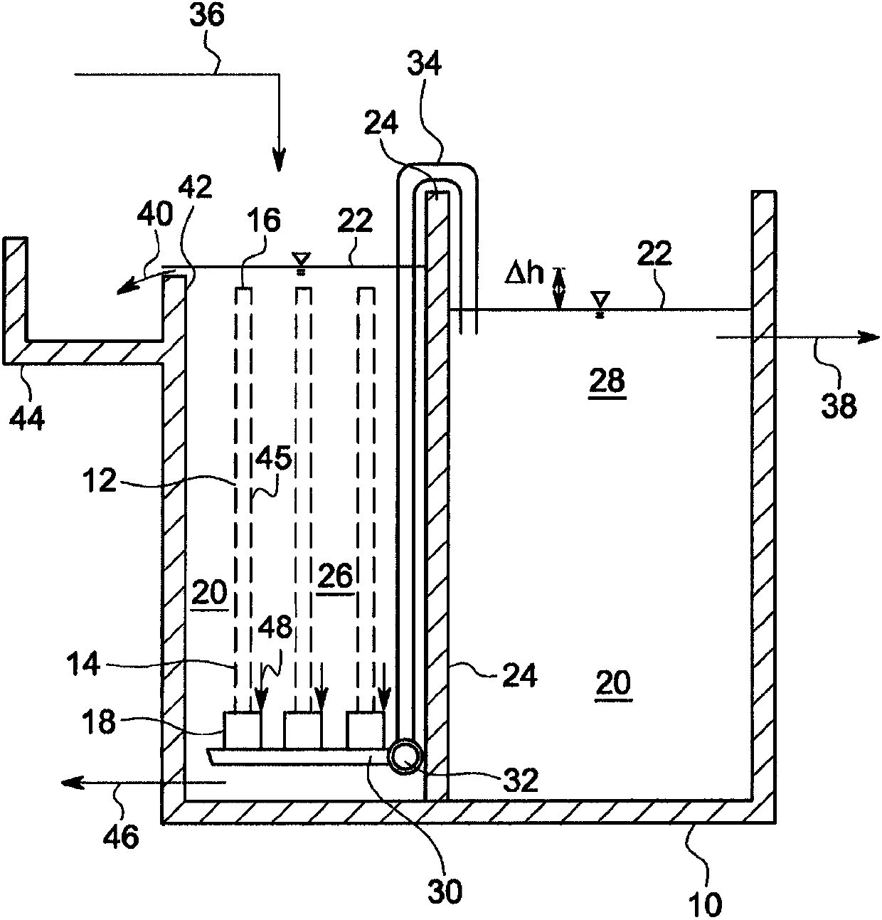
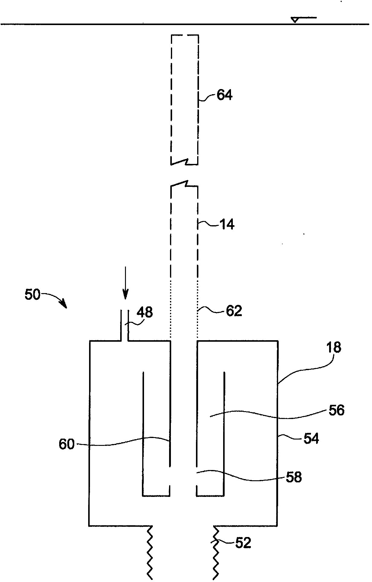
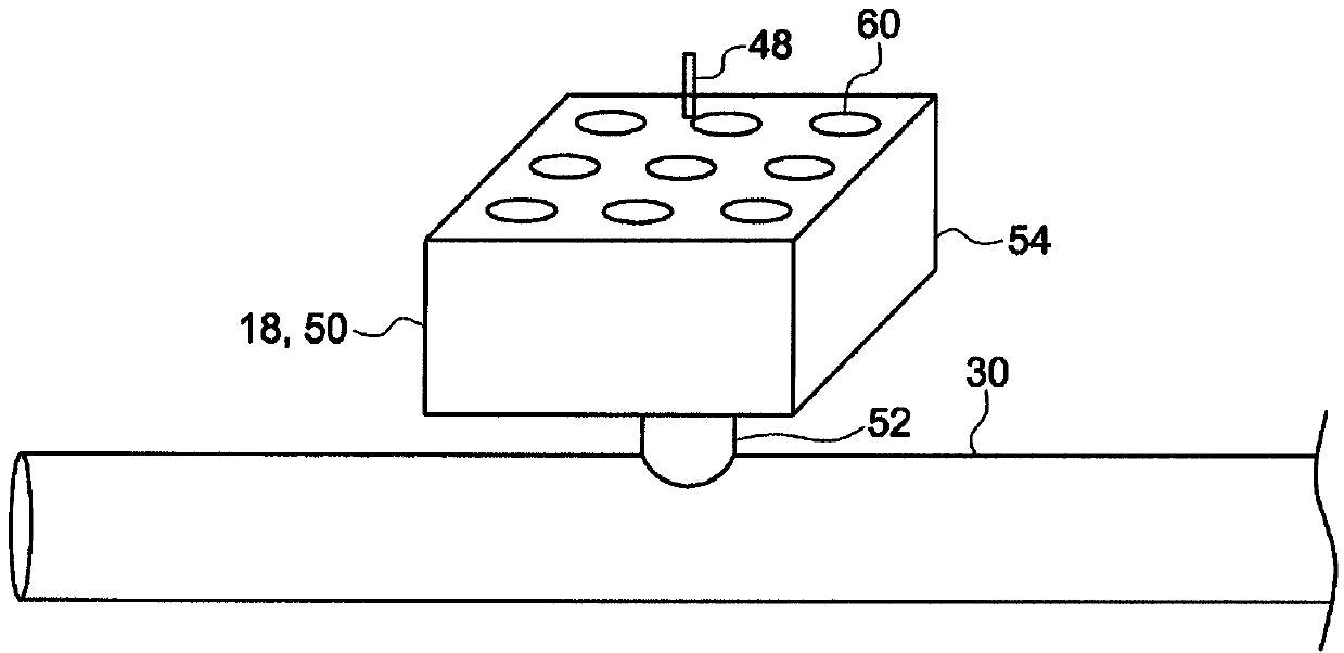
[0011] figure 1 Tank 10 containing static screen 12 is shown. The static sieve 12 has a plurality of filter bodies 14 . Each filter body 14 may be made from one or more layers of plastic or metal mesh that is rolled or folded into a prismatic conduit such as a tube. The top of the filter body 14 is covered by a cover 16 . The filter body 14 is open at the bottom and is attached to a pulse generating aerator 18 . As described further below, the pulse generating aerator 18 acts as an air driven backwashing device. A pulsating aerator 18 releases a slug of air or optionally a biphasic fluid into the filter body 14 from time to time. Although the pulsed aerator 18 will be described as operating with air, other gases may also be used.

[0012] The tank 10 is an aqueous open tank 20 having a free surface 22 upstream and downstream of a dividing wall 24 . A dividing wall 24 divides the tank 10 into an upstream portion 26 and a downstream portion 28 . Optionally, the downstream...


PUM


Abstract

A static screen has a plurality of screening bodies and a plurality of aeration devices downstream of the screening bodies. Each aeration device is associated with a set of one or more of the screening bodies. Each aeration device may be a pulsing aerator. The pulsing aerators do not all release air at the same time. Each screening body works through periods of dead end filtration separated by backwashing events. The backwashing events comprise introducing a slug or pulse of air into the bottom of the screening body. Flow through the static screen continues at all times because the screening bodies are not all backwashed at the same time. The static screen may be used to remove trash from water flowing to an immersed membrane unit. Alternatively, the static screen may be used to provide primary wastewater treatment.

Description

technical field [0001] The invention relates to a filter screen for filtering water, a method for operating the filter screen and a method for using the filter screen for water treatment. Background technique [0002] International Patent Publication No. WO 2007 / 131151 describes a static screen for use upstream of submerged membrane modules in membrane bioreactors. In some embodiments, the screen comprises a set of vertically oriented cylindrical filter bodies mounted in a storage tank. The filter body is open at its lower end and is connected to a collecting pipe near the bottom of the tank. The filtered water is collected in the collection pipe and can then be transported through the tank wall to feed the membrane modules. The aerator is located below the collecting pipe. In one process, air bubbles in the aerator are provided continuously at a low rate to discourage solids from settling on the filter. The air blow rate is periodically increased to reduce the density o...

Claims


Application Information

Patent Timeline
Patent Type & Authority Applications(China)
IPC IPC(8): C02F3/12B01D29/52B01D29/66B01D65/02B01D65/08C02F3/22B01F3/04
CPCC02F2303/16B01D2321/185B01D2201/087C02F3/1273B01D2321/04C02F3/223B01D65/08B01D2315/06B01D2313/26B01D65/02B01D2201/0476C02F2303/24B01F13/0266Y02W10/10B01F33/4062
Inventor P.L.科特J.R.卡明
Owner GENERAL ELECTRIC CO
Learn More