
Rapid processing device for precision parts

A processing device and precision parts technology, which is applied in the field of rapid processing devices for precision parts, can solve the problems of small inner wall diameter, irregular shape, and tolerance inner wall, etc.

Active Publication Date: 2016-10-05
KUNSHAN KERSEN SCI & TECH
View PDF7 Cites 0 Cited by
  • Summary
  • Abstract
  • Description
  • Claims
  • Application Information

AI Technical Summary

Problems solved by technology

[0004] The outer aluminum sleeve of this minimally invasive scalpel has a small inner wall diameter (5.86MM), and there is still a tolerance, and the inner wall has a special shape, and the special shape is very small (the width of the special shape is 0.7MM), and the ordinary method cannot make the inner wall small convex. point removal

Method used


Image

  • Rapid processing device for precision parts
  • Rapid processing device for precision parts
  • Rapid processing device for precision parts

Examples


Embodiment

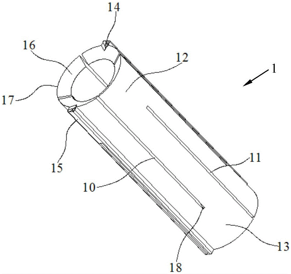
[0024] Embodiment: A rapid processing device for precision parts, including a circular insertion knife 1, a pressing mechanism 2, a push rod 3 and a precision part 4; the precision part 4 includes: an outer aluminum tube sleeve 5, an inner tube sleeve 6, a blade 7. The bar handle 8 and the knife bar 9, the knife bar 9 has a groove 91 at one end, the bar knife handle 2 has a rectangular cross section, and one end of the bar knife handle 2 is fixed to the groove of the knife bar 9 91, the blade 7 is welded to the side of the other end of the strip handle 2;

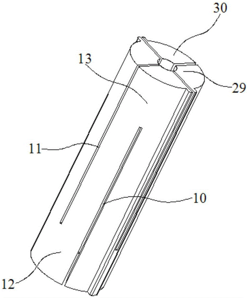
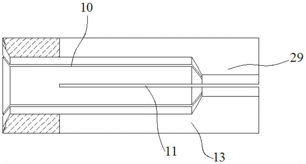
[0025] The circular slot 1 is provided with several first wire slots 10 and several second wire slots 11 in parallel along its axial direction, and the first wire slots 10 extend from one end surface of the round slot 1 to the circular The middle part of the insertion knife 1 thus forms several elastic blades 12, and the second wire through groove 9 extends from the other end face of the circular insertion knife 1 to the mi...


PUM

PropertyMeasurementUnit
angleaaaaaaaaaa

Abstract

The invention discloses a rapid machining device for a precision part. The rapid machining device for the precision part comprises a round slotting tool, a compression mechanism, an ejector rod and the precision part; the round slotting tool comprises elastic blades and elastic pieces; the internal surface of the elastic pieces are provided with protruding blocks; the protruding blocks are arranged at tail ends of the elastic pieces and accordingly a contact end face is formed in the other end of the round slotting tool; the compression mechanism comprises a cylinder, a piston and a cone cover; the cylinder is fixedly connected with the cone cover in a sealing mode; the piston is installed between the cylinder and the cone cover; a first chamber is formed between a piston rear end and the cylinder; a second chamber is formed between a piston front end and the cone cover; the piston front end is provided with a piston rod; the piston rod which extends to a chamber of the cone cover is matched with a central hole of the cone cover in a sliding seal mode; a piston rear end which extends out of a baffle plate is matched with a central hole of the baffle plate in a sliding seal mode; a chuck is installed inside the chamber of the cone cover; an external cone surface of the chuck and the internal wall of the cone cover are in sliding fit. The rapid machining device for the precision part can be in contact with the internal wall of an aluminum tube and not damage the internal wall and can remove small salient points on the internal wall maximally.

Description

technical field [0001] The invention relates to the field of medical instruments, in particular to a rapid processing device for precision parts. Background technique [0002] In the prior art, minimally invasive surgery is welcomed by patients because of its small trauma, light pain and quick recovery. However, due to the limitations of equipment and conditions, the operation has high requirements for doctors, but the process is very difficult. [0003] After long-term processing, it was found that the defect rate of the outer aluminum tube sleeve of the minimally invasive scalpel has remained high, and most of the processed parts cannot meet the precision requirements. The main reason is that the extrusion material is poorly fed, and small bumps of 0.05MM~0.1MM often appear on the inner wall of the aluminum agent material. However, this phenomenon cannot be improved in the aluminum agent process and bumps cannot be avoided. Therefore, it is necessary to improve the subse...

Claims


Application Information

Patent Timeline
Patent Type & Authority Patents(China)
IPC IPC(8): B23D13/00B23D9/00
Inventor 徐金根胡庆华
Owner KUNSHAN KERSEN SCI & TECH
Learn More