
Double-station riveting machine of permanent magnet type claw pole stepping motor speed reducer

A deceleration device and stepping motor technology, which is applied in the direction of assembly machines, manufacturing tools, metal processing equipment, etc., can solve the problems of motor deceleration device coordination, increased labor intensity, and prone to industrial accidents, etc., to achieve a high degree of automation, The effect of improving production efficiency and reducing production cost

Inactive Publication Date: 2014-08-13
中山明杰自动化科技有限公司
View PDF9 Cites 9 Cited by
  • Summary
  • Abstract
  • Description
  • Claims
  • Application Information

AI Technical Summary

Problems solved by technology

[0002] In the prior art, the riveting of the permanent magnet claw pole type stepping motor reducer adopts a semi-automatic machine. The gear shaft is automatically placed and the gear plate is manually installed, and then the machine is riveted. The upper magnetic plate and the gear plate are not riveted. This operation method requires Manual feeding increases labor intensity and is prone to industrial accidents. The upper magnetic plate and the gear plate are not riveted, and if they are installed in the stepping motor, the motor reducer may not cooperate smoothly.

Method used


Image

  • Double-station riveting machine of permanent magnet type claw pole stepping motor speed reducer
  • Double-station riveting machine of permanent magnet type claw pole stepping motor speed reducer
  • Double-station riveting machine of permanent magnet type claw pole stepping motor speed reducer

Examples


Embodiment Construction

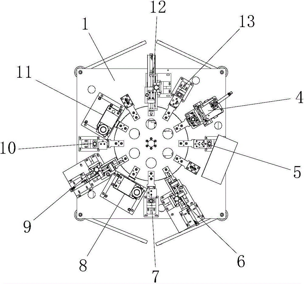
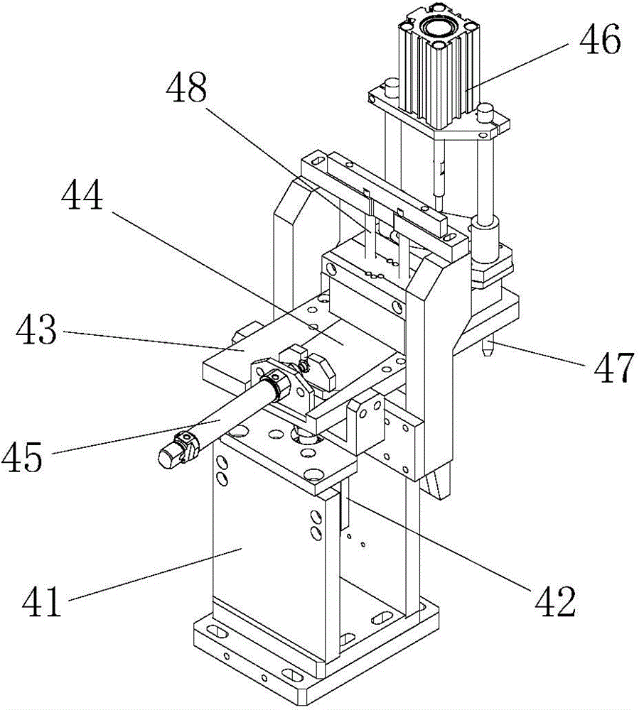
[0022] refer to Figure 1 to Figure 8 , a double-station riveting machine with a permanent magnet claw pole type stepping motor reduction device, including a machine platform 1, characterized in that a rotating disc 2 is installed on the machine platform 1, and a rotating disc 2 is installed on the rotating disc 2. There are a number of tooling positions 3, and the rotating disk 2 is connected with a rotating disk power mechanism to drive it to rotate. There are needle feeding mechanism 4, needle detection mechanism 5, gear plate feeding mechanism 6, first preload guiding mechanism 7, riveting mechanism 8, magnetic plate feeding mechanism 9, second preload guiding mechanism 10, and riveting mechanism 11. The material return mechanism 12 and the material return detection mechanism 13 .

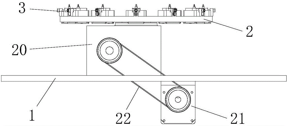
[0023] refer to figure 2 , the turntable power mechanism includes a special-shaped cam splitter 20 installed on the machine table 1, the rotating disk 2 is installed on the output shaft of t...


PUM


Abstract

The invention discloses a double-station riveting machine of a permanent magnet type claw pole stepping motor speed reducer. The double-position riveting machine comprises a machine which is provided with a rotating disc; the rotating disc is provided with a plurality of stations; the rotating disc is connected with a rotary table power mechanism used for driving the rotating disc to rotate; the machine is sequentially provided with a needle feeding mechanism, a needle detecting mechanism, a gear plate transmission mechanism, a first pre-pressing correction mechanism, a riveting pressure mechanism, an upper magnetic plate transmission mechanism, a second pre-pressing correction mechanism, an overlapped riveting mechanism, a material return mechanism and a material return detection mechanism along the rotating direction of the rotating disc; the plurality of stations are used for alternate operation at the same time, and a mode of one mould and two holes is adopted, so that high-efficiency production can be realized; the automatic discharging and riveting work of the permanent magnet type claw pole stepping motor speed reducer can be completed within a work period, and a produced upper magnetic plate is riveted with a gear plate, so that the performances of the stepping motor speed reducer is stable, the degree of automation is high, the traditional manual operation is replaced by the double-position riveting machine, the product quality is effectively controlled, the production efficiency is increased, and the production cost is lowered.

Description

technical field [0001] The invention relates to a micro-special motor manufacturing machine, in particular to a double-station riveting machine for a permanent magnet claw pole type stepping motor output shaft reduction device. Background technique [0002] In the existing technology, the riveting of the permanent magnet claw pole type stepping motor reduction device adopts a semi-automatic machine, the gear shaft is automatically placed and the gear plate is manually installed, and then the machine is riveted. The upper magnetic plate and the gear plate are not riveted. This operation method requires Manual feeding increases the labor intensity of people and is prone to industrial accidents. The upper magnetic plate and the gear plate are not riveted, and if they are installed in the stepping motor, the motor reduction device may not cooperate smoothly. Contents of the invention [0003] In order to overcome the deficiencies of the prior art, the present invention provide...

Claims


Application Information

Patent Timeline
IPC IPC(8): B23P21/00
CPCB23P21/006
Inventor 李遵杰周建龙成镇明
Owner 中山明杰自动化科技有限公司
Learn More