Elevator brake performance whole process real-time monitoring control system and using method

An elevator brake and real-time monitoring technology, which is applied in elevators, hoisting devices, transportation and packaging, etc., can solve the problems of no safety guarantee, achieve the effects of reducing maintenance costs, preventing accidents, and high reliability

Active Publication Date: 2014-08-13
ZHEJIANG COLLEGE OF ZHEJIANG UNIV OF TECHOLOGY
6 Cites 21 Cited by

AI-Extracted Technical Summary

Problems solved by technology

Jumping to the top or squatting accidents are generally caused by the failure of the brake of the elevator. The brake is a very important part of the elev...

Abstract

The invention discloses an elevator brake performance whole process real-time monitoring control system and a using method. According to the elevator brake performance whole process real-time monitoring control system, a spring pressure detecting system, a friction force detecting system and a band-type brake frequency detecting system are respectively mounted on an elevator brake. Real-time whole process monitoring can be conducted on the elevator brake. The working state of the elevator brake can be judged in advance, early warning can be given out in time, and accidents are avoided. Maintenance cost can be reduced, and meanwhile the system is low in cost and high in reliability.

Application Domain

Technology Topic

Image

  • Elevator brake performance whole process real-time monitoring control system and using method
  • Elevator brake performance whole process real-time monitoring control system and using method
  • Elevator brake performance whole process real-time monitoring control system and using method

Examples

  • Experimental program(1)

Example Embodiment

[0024] Example 1
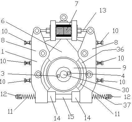
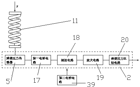
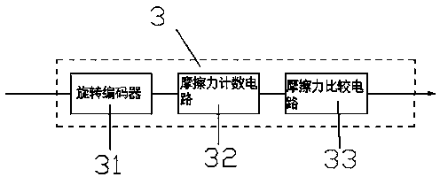
[0025] Such as Figure 1-5 As shown, an elevator brake performance full-process real-time monitoring and control system and its use method include an elevator brake 1. A spring pressure detection system 2, a friction detection system 3, and a brake frequency detection system 4 are respectively installed on the elevator brake 1.
[0026] The elevator brake 1 includes a bracket 6 on which an electromagnet 7, two brake arms 8, and a brake wheel 9 are respectively installed. The electromagnet 7 is located between the two brake arms 8, and the electromagnet 7 is used to reset the brake spring 11. The brake wheel 9 is located between the two brake arms 8, a rotating shaft 30 is installed on the brake wheel 9, and a friction detection system 3 and a brake frequency monitoring system are installed between the brake wheel 9 and the rotating shaft 30 In the system 4, a positioning bolt 10, a brake shoe 36 and a brake spring 11 are respectively installed on the brake arm 8. The positioning bolt 10 is used to fix and adjust the position of the elevator brake 1. A brake lining 37 is installed on the brake shoe 36. The brake lining 37 can better increase the braking force. The brake spring 11 is equipped with a brake spring adjusting nut 12 and a spring pressure detection system 2. The brake spring adjusting nut 12 can adjust the spring pressure of the brake spring 11 when it is not braked. An electromagnet installation rod 13 is erected between the two brake arms 8, and an electromagnet 7 is installed on the electromagnet installation rod 13. Two manual brake release cams 14 are installed between the two brake arms 8. The manual brake release cam 14 can release the pressure of the pressure spring when the elevator fails, thereby releasing the brake. A brake spring screw 15 is erected between the manual brake release cam 14.
[0027] The spring pressure detection system 2 includes a spring pressure sensor 5 installed on the brake spring 11, and the spring pressure sensor 5 is connected to the first bridge circuit 17 through an electric circuit. The first bridge circuit 17 is connected to the filter circuit 18 through a circuit. The filter circuit 18 is used for the filter circuit to filter high frequency interference. The filter circuit 18 is connected to the amplifying circuit 19 and the second bridge circuit 39 through circuits, respectively. The second bridge circuit 39 can realize temperature compensation of the corresponding strain. The amplifying circuit is used to amplify the pressure signal. The amplifying circuit 19 is connected to the spring pressure comparison circuit 20 through a circuit. The spring pressure comparison circuit 20 compares the pressure signal with a preset value.
[0028] The friction force detection system 3 includes a rotary encoder 31 installed between the brake wheel 9 and the rotating shaft 30, and the rotary encoder 31 is connected to the friction force counting circuit 32 through a circuit. The friction force counting circuit 32 counts the signals measured by the rotary encoder 31. The friction force counting circuit 32 is connected to the friction force comparing circuit 33 through a circuit. The friction force comparison circuit 33 compares the friction force signal with a preset value.
[0029] The brake detection system 4 includes a rotary encoder 31 installed between the brake wheel 9 and the rotating shaft 30. The rotary encoder 31 is connected to a shaping circuit 34 through an electric circuit, and the shaping circuit 34 opposes the rotary encoder 31. The measured signal is shaped. The shaping circuit 34 is connected to the brake counting circuit 35 through a circuit. The brake counting circuit 35 counts the brake actions and compares it with a preset value.
[0030] The rotary encoder 31 includes an encoder shaft 21 and a housing 22. A grating plate 23 is installed on the encoder shaft 21. A light-emitting diode 24, a prism 25, a fixed grating 26 and two photosensitive tubes are installed on the housing 22. The light-emitting diode 24, the prism 25 and the fixed grating 26 are located in the same straight line, a grating plate 23 is installed between the prism 25 and the fixed grating 26, and the light-emitting diode 24 is connected to an external power source through a circuit. When the encoder shaft 21 is relatively offset from the rotary encoder 31, the light signal from the light emitting diode 24 received by the photosensitive tube changes. The first photosensitive tube 27 is connected to the friction counting circuit 32 through a circuit, and the second photosensitive tube 28 is connected to the shaping circuit 34 through a circuit.
[0031] A working method of the elevator brake performance real-time monitoring and control system:
[0032] 1) When a brake signal is received, the brake spring 11 will act to displace the brake arm 8 inward, driving the brake shoe 36 and the brake lining 37 to move towards the brake wheel 9, causing the brake lining The material 37 is in contact with the brake wheel 9 to generate braking force;
[0033] 2) At the same time, the pressure signal measured by the spring pressure sensor 5 is transmitted to the filter circuit 18 via the first bridge circuit 17. At the same time, the second bridge circuit 39 realizes the temperature compensation of the corresponding strain, and the filter circuit 18 filters out high-frequency interference , Amplified by the amplifier circuit 19, sent to the spring pressure comparison circuit 33 for comparison with the preset signal, if the spring pressure is less than the preset value, output an alarm signal;
[0034] 3) At the same time, the brake wheel 9 decelerates from the rotating shaft 30 due to the braking force, and the offset signal is measured by the rotary encoder 31, which is transmitted to the friction force comparison circuit 33 through the friction force counting circuit 32 for comparison. The preset amount indicates that the braking friction is too small and an alarm signal is output;
[0035] 4) At the same time, the signal measured by the rotary encoder 31 is transmitted to the brake counting circuit 35 through the shaping circuit 34. The brake counting circuit 35 records the number of brakes. When the number of brakes exceeds a preset value, an alarm signal is output.

PUM

no PUM

Description & Claims & Application Information

We can also present the details of the Description, Claims and Application information to help users get a comprehensive understanding of the technical details of the patent, such as background art, summary of invention, brief description of drawings, description of embodiments, and other original content. On the other hand, users can also determine the specific scope of protection of the technology through the list of claims; as well as understand the changes in the life cycle of the technology with the presentation of the patent timeline. Login to view more.

Similar technology patents

Lifting hook of hoist crane

Owner:常熟市海鸥机械有限责任公司

Yield-to-pedestrian detection system

Owner:武汉元鼎创天信息科技有限公司

Classification and recommendation of technical efficacy words

  • Reduce maintenance costs
  • Avoid accidents
Why Eureka
Try Eureka