
Metal-head box of hot continuous rolling production line

A rolling production line and iron head box technology, which is applied in the field of hot rolling iron head transportation equipment, can solve the problems that the iron head card is not easy to unload, the wire rope sleeve is easy to fall off, and affects the production rhythm, etc., so as to shorten the loading time, Good safety performance and the effect of improving loading efficiency

Inactive Publication Date: 2014-08-13
JIGANG GRP
View PDF6 Cites 0 Cited by
  • Summary
  • Abstract
  • Description
  • Claims
  • Application Information

AI Technical Summary

Problems solved by technology

[0003] The existing iron head box is provided with lifting lugs on the four sides of the box body. When the iron head box is lifted out of the iron head pit or put in, it is necessary to manually hang the steel wire rope and manually pick the steel wire rope. The cooling water of the shears falls into the pit, so the operator must stop the rolling when entering the iron head pit, otherwise there will be danger to life. However, it takes about ten minutes for manual operation to change a iron head box, and the rolling must be stopped, which will seriously affect Production rhythm; At the same time, it is necessary to use a wire rope to cover the lifting lug. The wire rope is easy to fall off during use, and there is a great safety hazard. Circular rotation, during the dumping process of the iron head, there is a phenomenon that the iron head is scattered outside the transport vehicle, and there is also the problem that the iron head is stuck in the iron head box and is not easy to unload

Method used


Image

  • Metal-head box of hot continuous rolling production line
  • Metal-head box of hot continuous rolling production line
  • Metal-head box of hot continuous rolling production line

Examples


Embodiment Construction

[0027] The technical solutions of the present invention will be described in detail below in conjunction with the accompanying drawings.

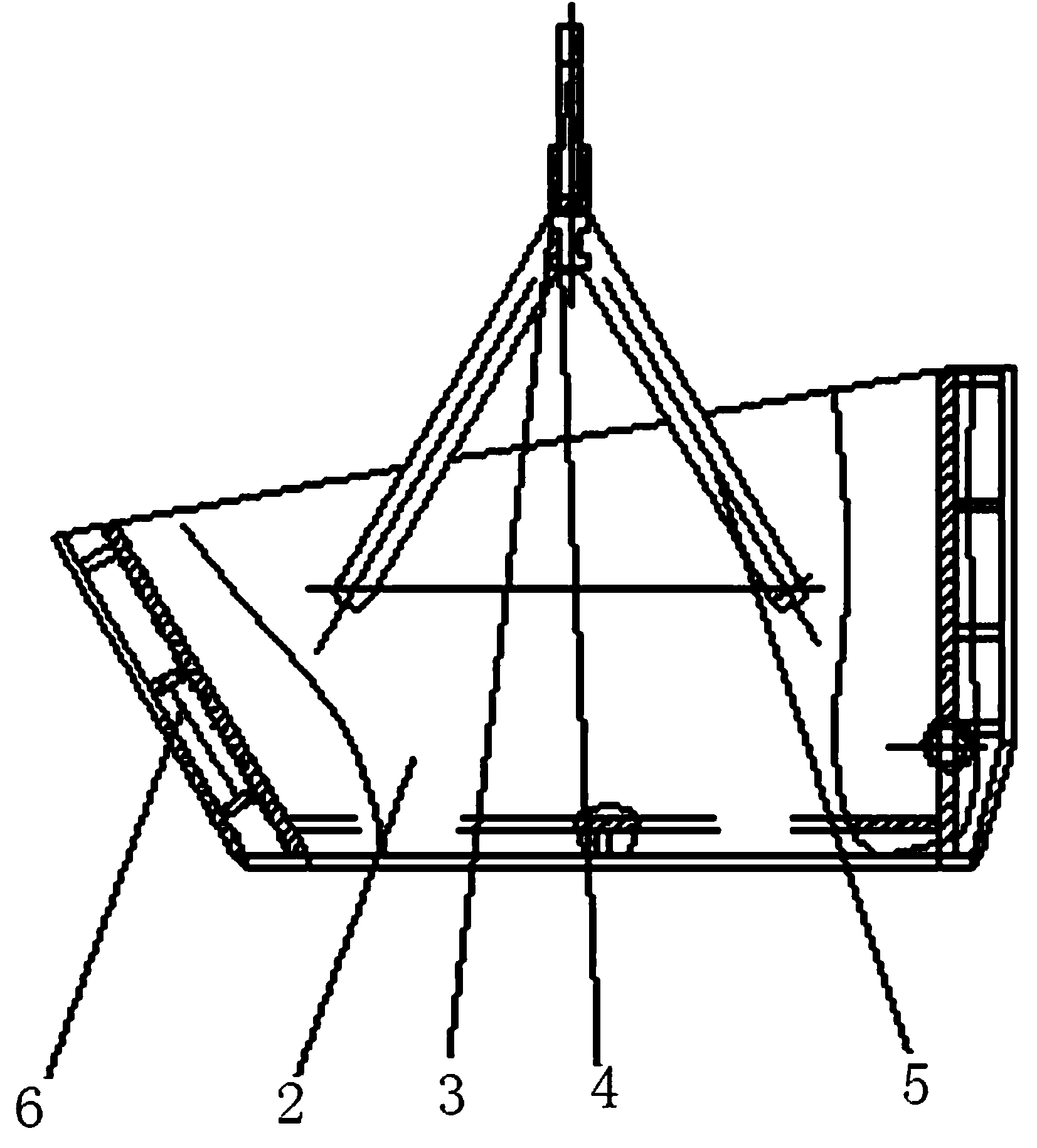
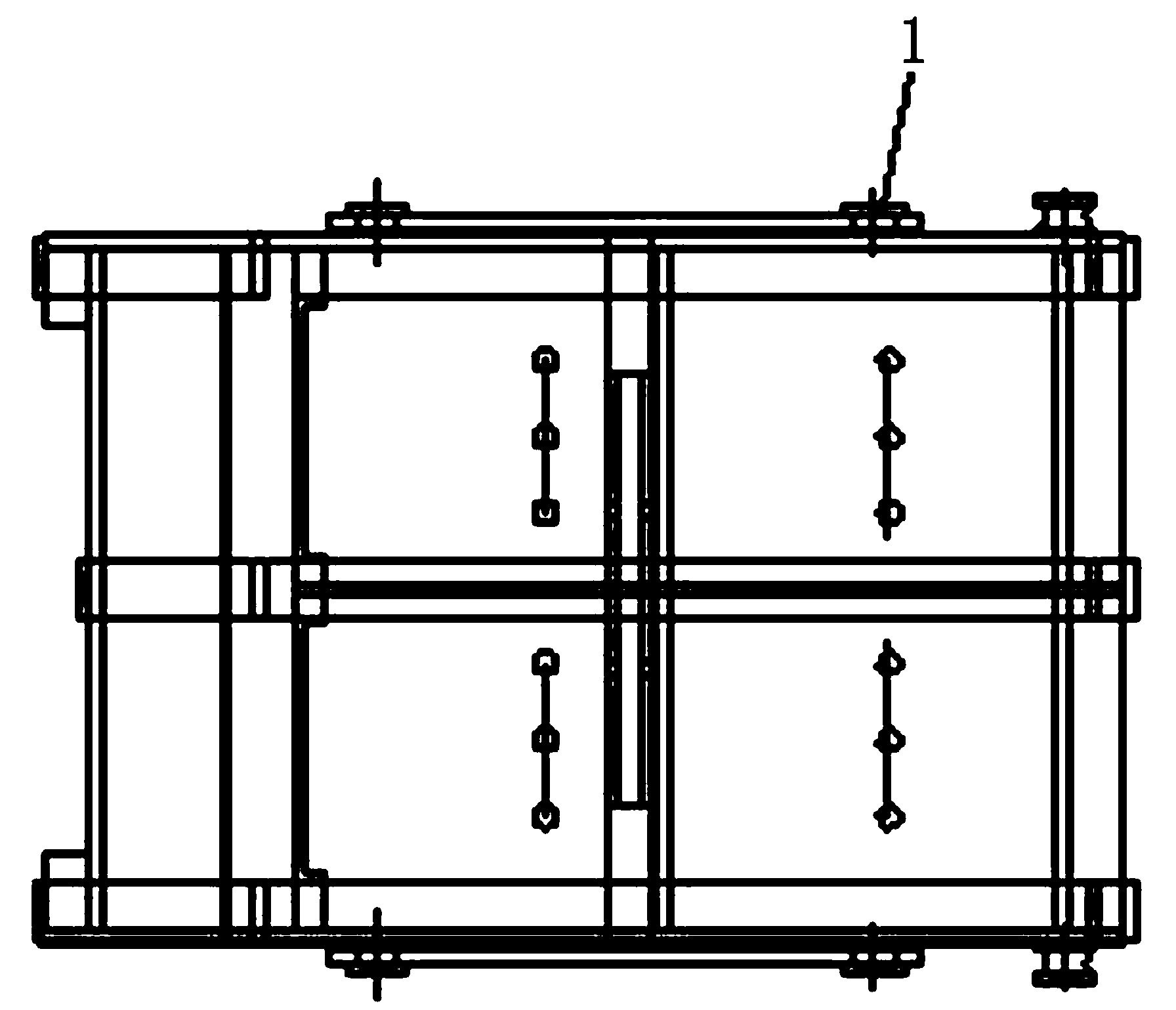
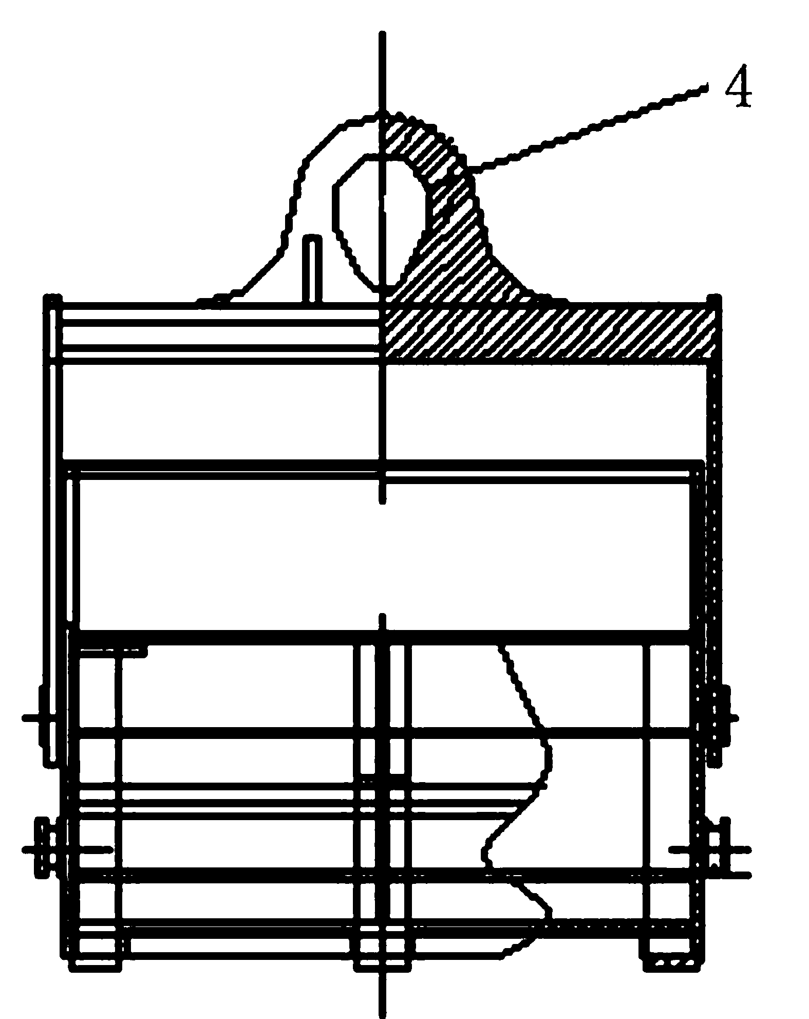
[0028] Such as Figure 1 to Figure 6 As shown, the iron head box of the hot continuous rolling production line of the present invention includes a box body 2, the left surface and the right surface of the box body 2 are fixed with cantilever arms, and the top of the cantilever arms is arranged on the top surface of the box body 2 , the cantilever arm is composed of two cantilever beams 5 fixedly connected at the top and arranged at a certain angle, the other end of the cantilever beam 5 is fixed on the box body 2, and the top ends of the two cantilever arms are fixedly connected by a crossbeam 3, which is provided with a hanging hole 4. The front surface of the box body 2 is inclined relative to the lower bottom surface and the length of the upper top surface is greater than the length of the lower bottom surface.

[0029] By setting canti...


PUM


Abstract

The invention relates to transport equipment of a hot continuous rolling metal head, and in particular relates to a metal-head box of a hot continuous rolling production line. The metal-head box of the hot continuous rolling production line comprises a box body, wherein suspension beam arms are fixedly arranged on the left surface and the right surface of the box body; the top ends of the suspension beam arms are arranged above the upper top surface of the box body; the suspension beam arms are composed of two suspension beams of which the top ends are fixedly connected with each other, and a certain included angle is arranged between the two suspension beams; the other ends of the suspension beams are fixed to the box body; the top ends of the two suspension beam arms are fixedly connected with each other through a cross beam; a hoisting hole is formed in the cross beam; the front surface of the box body is obliquely arranged relative to the bottom surface, and the upper top surface is longer than the lower bottom surface. The metal-head box of the hot continuous rolling production line has the advantages of being easily loaded and unloaded, and reliable to use.

Description

technical field [0001] The invention relates to a hot continuous rolling iron head transportation equipment, in particular to a hot continuous rolling production line iron head box. Background technique [0002] In the hot continuous rolling production line, there are two iron heads for every piece of steel rolled. The iron heads cut by flying shears are collected by the iron head collection device, namely the iron head box. The iron head box is usually set at a depth of 8 meters below the plant floor. In the iron head pit, during the production process, the rolling rhythm is generally about two minutes to roll one piece, that is to say, two iron heads will fall into the iron head pit every two minutes. The iron heads need to transport more than a dozen boxes of iron heads. [0003] The existing iron head box is provided with lifting lugs on the four sides of the box body. When the iron head box is lifted out of the iron head pit or put in, it is necessary to manually hang ...

Claims


Application Information

Patent Timeline
Patent Type & Authority Applications(China)
IPC IPC(8): B66C1/16
Inventor 王克柱刘宁李文刘恒文赵磊郭宏伟
Owner JIGANG GRP
Learn More