An all-wheel drive transfer case electronic control device

An electronic control device and all-wheel drive technology, which is applied in the direction of transmission control, belt/chain/gear, and components with teeth, can solve problems such as error-prone, cumbersome operation, and low efficiency, so as to prolong life and avoid Abrasion or damage, the effect of reducing losses

Active Publication Date: 2016-08-17
XUZHOU XUGONG AUTOMOBILE MFG CO LTD
View PDF6 Cites 0 Cited by
  • Summary
  • Abstract
  • Description
  • Claims
  • Application Information

AI Technical Summary

Problems solved by technology

In the absence of an all-wheel drive transfer case electronic control device, on the one hand, it is impossible to effectively realize the function of gearbox speed reduction and torque increase and the transfer case is distributed to each drive axle in a certain proportion; error prone

Method used


Image

  • An all-wheel drive transfer case electronic control device
  • An all-wheel drive transfer case electronic control device
  • An all-wheel drive transfer case electronic control device

Examples


Embodiment 1

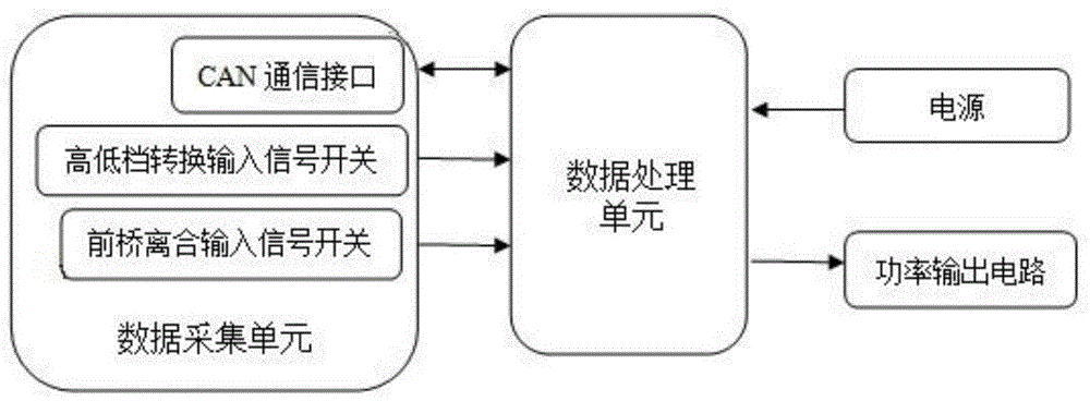
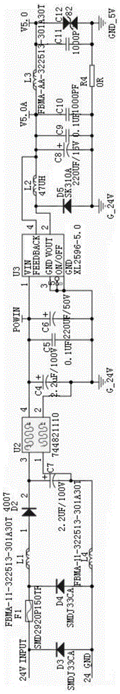
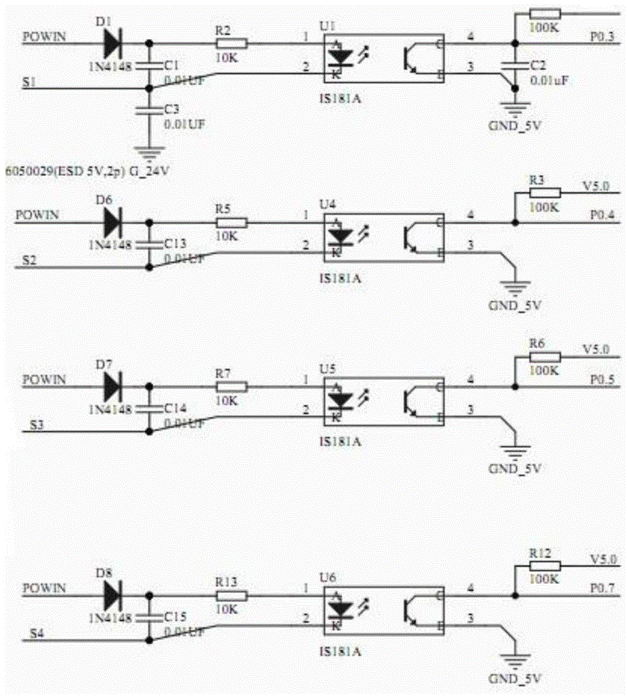
[0022] Such as figure 1 The shown electronic control device for an all-wheel drive transfer case includes a main control data processing unit, a data acquisition unit for signal acquisition, a power supply, and a power output unit connected to the data processing unit. The data acquisition unit includes a high-low gear conversion input signal switch, a front axle clutch input signal switch, and a CAN communication interface; the data processing unit is used to calculate and compare the collected data, and according to the calculation and comparison results The power of each channel is output through the power output unit. The schematic diagram of each part of the circuit is as follows Figure 2-Figure 6 shown.

Embodiment 2

[0023] Embodiment 2 The transfer control device described in Embodiment 1 implements the control method

[0024] a. High-end and low-end mode conversion:

[0025] Press the high and low shift switch button, when the corresponding high or low gear indicator lights up, the transfer case is in the high or low gear state, at this time release the control switch, the transfer case is in the high or low gear state.

[0026] The solenoid valve is controlled by the corresponding switch, and the high and low gear air circuit is used to realize the conversion of high and low gear. Figure 7 As shown, 1 inlet air, the pressure F pushes the two pistons to move to the left to the limit position, the piston pushes the fork shaft to the left, the fork handle is pushed to the left with the gear sleeve, and the gear sleeve is connected with the input shaft and the low gear at the same time. Engaged, power is transmitted through the low gear teeth, and the transfer case is in the low gear to c...

Embodiment 3

[0031] 1) The logic description of the control device described in Embodiment 1 is shown in Table 1

[0032] Table 1 Logic description table of the control device described in Embodiment 1

[0033]

[0034] 2) The wiring principle of the control device described in the present invention is as follows: Figure 9 and shown in Table 2

[0035] Table 2 Description of the wiring principle of the control device of the present invention

[0036]


PUM


Abstract

The invention discloses an electric control device of an all-wheel drive transfer case. The electric control device comprises a data processing unit, a data acquisition unit, a power supply and a power output unit, wherein the data acquisition unit, the power supply and the power output unit are all connected with the data processing unit. By applying the electric control device, all states of the transfer case can be switched better and more safely; therefore the service life of a transmission system is prolonged, and the use requirement of the transfer case at the aspect of power matching is met.

Description

technical field [0001] The invention belongs to the field of automobile electrics, and in particular relates to an electric control device for an all-wheel drive transfer box. Background technique [0002] Because the car is running on different road conditions, especially in the case of bad road conditions, the power of the general drive type car cannot be effectively distributed to the front axle when the vehicle is climbing, making it difficult for the vehicle to climb the slope. , The adhesion coefficient between the tire and the ground cannot meet the driving requirements, thereby increasing the power consumption of the vehicle and the wear of the drive train components and tires. [0003] In order to further increase the output torque of the gearbox (change the transmission ratio) and play the role of reducing speed and increasing torque, the transfer box is equipped with high and low gears, which can expand the transmission ratio and the number of gears when driving i...

Claims


Application Information

Patent Timeline
Patent Type & Authority Patents(China)
IPC IPC(8): F16H61/18F16H61/30F16H63/44
CPCF16H61/0006F16H61/18F16H63/44
Inventor 李建明赵建东刘步杰姚宝山刘贤丁琦刘明
Owner XUZHOU XUGONG AUTOMOBILE MFG CO LTD
Why Eureka
Try Eureka