A banknote storage device

A technology for storage devices and banknotes, applied to devices for accepting coins, handling coins or valuable banknotes, instruments, etc., which can solve problems such as rising product costs, complex structures, and bulky volumes

Inactive Publication Date: 2017-02-22
SHENZHEN BROADZONE INTELLIGENCE TECH CO LTD
View PDF7 Cites 0 Cited by
  • Summary
  • Abstract
  • Description
  • Claims
  • Application Information

AI Technical Summary

Problems solved by technology

The banknote storage devices commonly used today include banknote storage boxes, banknote feeding mechanisms and banknote output mechanisms. However, due to their unreasonable structural design, it is impossible to withdraw multiple banknotes for one-time purchase, or although it can be realized once. Withdrawing multiple banknotes invested in one purchase, but its structure is complex and bulky, resulting in a substantial increase in product costs. The high cost prevents it from being widely used in commonly used outdoor unattended equipment, such as vending machines, Banknote consumer financial equipment such as currency exchange machines
Commonly used banknote storage devices also have the problem of being unable to store a large number of banknotes, and frequently fail during the process of depositing or withdrawing banknotes

Method used


Image

  • A banknote storage device
  • A banknote storage device
  • A banknote storage device

Examples


Embodiment 1

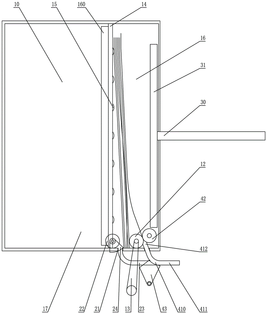
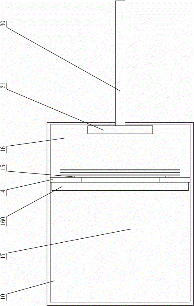
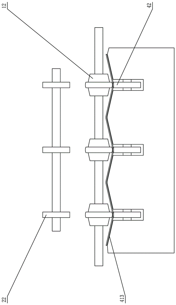
[0036] Such as figure 1 , 2 , Figure 15 As shown, the banknote storage device includes a banknote feeding mechanism, which includes a banknote feeding wheel 42 that the intermediate wheel 12 can cooperate with when feeding banknotes. The intermediate wheel 12 or the banknote feeding wheel 42 can be selected as a driving wheel for providing power, or both can be driving wheels for providing power. In this embodiment, the driving wheel providing power is the intermediate wheel 12 . When described intermediate wheel 12 was cooperated with described banknote-advancing wheel 42, the distance between the axis line of described intermediate wheel 12 and the inner side of the box wall where described banknote outlet 21 was located was less than the axis line and The distance from the inner side of the box wall where the cash outlet 21 is located. The money-in mechanism also includes a banknote-in channel 410, and the banknote-in channel 410 includes an outer end 411 of the banknote...

Embodiment 2

[0043] The difference between the second embodiment and the first embodiment is that the storage box 10 includes a temporary storage area 16, a storage area 17, and a passage accommodating area 18, and a passage opening 413 is provided on the passage accommodating area 18, and the banknote feeding passage The outer end 411 extends to the outside of the storage box 10 through the passage opening 413 . Described banknote-advancing channel 410 is the structure that is connected with storage box mounting bracket 20, and storage box is installed on the storage box 10 mounting bracket 20, and the banknote-advancing channel inner end 412 of described banknote-advancing channel 410 will just be close to described Advance bank note wheel 42.


PUM


Abstract

Disclosed is a bill storage device which includes a storage box and a bill entrance mechanism and a bill exit mechanism, which are arranged on the storage box. The bill exit mechanism is arranged at one side of the bill entrance mechanism. The bill exit mechanism includes a bill exit port arranged on the storage box and a bill withdrawing wheel arranged in the storage box and on an edge of the bill exit port. The storage box includes a temporary storage area and a storage area. Both of the bill exit mechanism and the bill entrance mechanism are arranged in the temporary storage area. An intermediate wheel, a rotating shaft of which is capable of moving, is also arranged in the temporary storage area. The intermediate wheel cooperates with the bill withdrawing wheel when bills exit. When the bills exit, the intermediate wheel moves towards the bill withdrawing wheel and because the rotating shaft of the intermediate wheel is capable of moving, when the bills exit, a gap between the intermediate wheel and the bill withdrawing wheel can be adjusted according to the thickness of bills which are withdrawn so that it is ensured that the withdrawn bills can successfully exit.

Description

technical field [0001] The invention relates to a banknote storage device, in particular to a banknote storage device with a temporary storage area and capable of withdrawing a plurality of banknotes from the temporary storage area at one time. Background technique [0002] With the development of science and technology, many public places are now equipped with vending machines, currency exchange machines or deposit machines in order to meet people's needs for convenience and speed, which greatly saves the configuration of human resources. As a key part of the aforementioned automatic vending machine, currency exchange machine or deposit machine, etc., the banknote storage device is widely used in the commercial field. Banknote storage devices are divided into coin storage devices and banknote storage devices. Due to the small value of coins, the application range of coin storage devices is relatively narrow. Compared with coin storage devices, the application range of bankn...

Claims


Application Information

Patent Timeline
Patent Type & Authority Patents(China)
IPC IPC(8): G07D11/00
Inventor 顾成武侯兰忠
Owner SHENZHEN BROADZONE INTELLIGENCE TECH CO LTD
Why Eureka
Try Eureka