Eureka AIR delivers breakthrough ideas for toughest innovation challenges, trusted by R&D personnel around the world.

Cathode protective potential monitoring system for buried metal pipeline

A cathodic protection and potential monitoring technology, applied in the direction of electrical signal transmission system, signal transmission system, measuring device, etc., can solve the problem that the method of collecting cathodic protection data has not been improved, and it is difficult to meet the needs of real-time detection of pipeline cathodic protection, etc. Achieve the effects of saving labor costs, satisfying real-time detection, and improving detection efficiency

Inactive Publication Date: 2014-08-13
王辉
View PDF6 Cites 22 Cited by
  • Summary
  • Abstract
  • Description
  • Claims
  • Application Information

AI Technical Summary

Problems solved by technology

So far, the collection of cathodic protection data for most pipelines in China relies on manual line inspection. According to the relevant provisions of the national standard "Technical Specifications for Cathodic Protection of Buried Steel Pipelines" GB / T21448-2008: the cathodic protection of the forced current system Routine function testing is carried out once a month to three months. The staff members pass through the test piles of the pipeline regularly and regularly. For gas pipelines under anode protection, the development of an online monitoring system that can remotely monitor the potential of each position of the pipeline and has functions such as real-time data display, historical data callback, analysis and early warning, and pipeline abnormal point location is the key to normal production operations, An Important Guarantee for Eliminating Potential Safety Hazards

Method used


Image

  • Cathode protective potential monitoring system for buried metal pipeline
  • Cathode protective potential monitoring system for buried metal pipeline
  • Cathode protective potential monitoring system for buried metal pipeline

Examples


Embodiment Construction

[0019] The present invention will be further described in detail below in conjunction with the accompanying drawings.

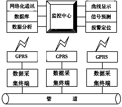
[0020] figure 1 It is the overall principle block diagram of the cathodic protection potential monitoring system for buried metal pipelines. The system includes a monitoring center and a number of data acquisition terminals. Several data acquisition terminals are distributed in different measurement positions of the tested pipeline 3, and are used to measure the potential of different positions on the tested pipeline 3. The monitoring center is used to receive various data. The detection data fed back by the terminal is collected, and the detection data is stored in the database for real-time data display and historical data callback. At the same time, it is supplemented by the data analysis function of the monitoring center to realize the functions of signal prediction and alarm and pipeline abnormal point positioning.

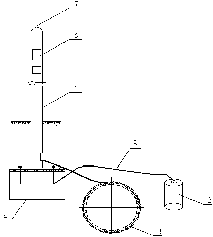
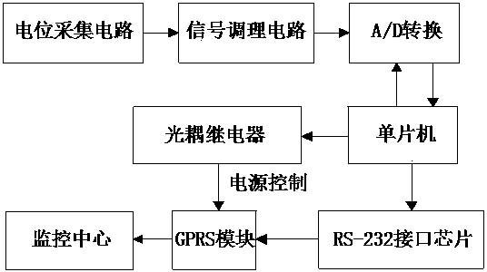
[0021] figure 2 is the structure ...


PUM


Abstract

The invention discloses a cathode protective potential monitoring system for a buried metal pipeline. The cathode protective potential monitoring system comprises a monitoring center and a plurality of data collection terminals, wherein the plurality of data collection terminals are distributed on different measuring positions of a measured pipeline and used for measuring the potential on different positions of the measured pipeline, the monitoring center is used for receiving the detection data fed back by each data collection terminal, storing the detection data into a database, displaying real-time data and calling back the historical data, and functions for predicting and alarming a signal and locating an abnormal point of a pipeline can be realized through the assistance of a data analysis function of the monitoring center. The cathode protective potential monitoring system for the buried metal pipeline is used for remote monitoring, so that compared with the manual regular inspection, the requirement for the real-time detection of cathode protective parameter of the pipeline can be better met, the detection efficiency also can be greatly improved, and the labor cost can be reduced.

Description

technical field [0001] The invention relates to a monitoring device for monitoring the anticorrosion performance of buried metal pipelines, in particular to a cathodic protection potential monitoring system for buried metal pipelines. [0002] Background technique [0003] With the development of the petroleum industry, the use of buried metal pipelines for gas transportation has become an important way of domestic natural gas transportation. In order to maximize the service life of the pipeline and ensure the safe operation of the pipeline, it is necessary to improve the cathodic protection efficiency of the pipeline and improve Cathodic protection measures, and the monitoring of cathodic protection status and accurate analysis of the acquired data are crucial. So far, the collection of cathodic protection data for most pipelines in China relies on manual line inspection. According to the relevant provisions of the national standard "Technical Specifications for Cathodic P...

Claims


Application Information

Patent Timeline
Patent Type & Authority Applications(China)
IPC IPC(8): G08C19/00G01N17/00
Inventor 王辉朱曦
Owner 王辉
Why Eureka
Eureka Blog
Learn More