Group of shift registers and method of driving them

A shift register and group technology, applied in static memory, digital memory information, instruments, etc., can solve problems such as time reduction and abnormal display screen, and achieve the effect of speeding up the pull-down speed

Active Publication Date: 2016-11-16
AU OPTRONICS CORP
View PDF8 Cites 0 Cited by
  • Summary
  • Abstract
  • Description
  • Claims
  • Application Information

AI Technical Summary

Problems solved by technology

[0003] However, since each scanning line on the screen is generally driven by a corresponding gate driving circuit, as the picture fineness increases and the frame update rate increases, each gate driving circuit is used to drive the corresponding scanning line. The time the output signal is in the enabled state corresponds to a sharp decrease
Assuming that the output signal of the gate drive circuit of the Nth stage is still enabled when the scanning of the corresponding Nth scanning line is completed, then it will only be provided to the N+1th scanning line. The data of the electrically coupled pixels are simultaneously charged into the pixels electrically coupled with the Nth scan line, causing abnormalities in the display screen
That is to say, the output signal of each gate drive circuit must be quickly pulled down to a non-enabled state, otherwise it may cause abnormalities in the display screen

Method used


Image

  • Group of shift registers and method of driving them
  • Group of shift registers and method of driving them
  • Group of shift registers and method of driving them

Examples


Embodiment Construction

[0064] The following describes the present invention in detail with reference to the drawings and specific embodiments, but it is not intended to limit the present invention.

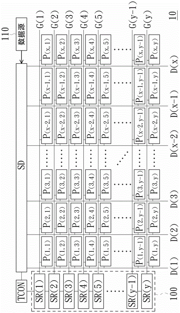
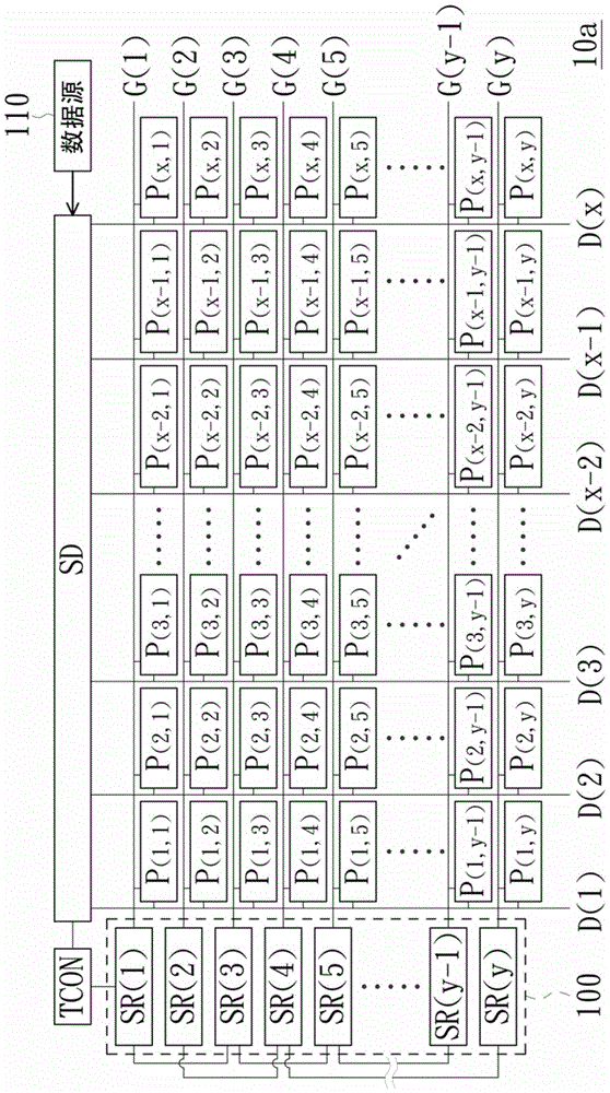
[0065] Please refer to Figure 1A , Which is a circuit block diagram of a flat panel display used in an embodiment of the present invention. In this embodiment, the flat panel display 10 includes a timing controller (Timing-Controller) TCON, a data driver SD, a shift register group 100, a plurality of data lines D(1) to D(x), respectively Transmit output signals G(1)~G(y) multiple scan lines, and multiple pixels P (1,1) ~P (x,y) . Among them, the timing controller TCON provides clock signals and control signals to the data driver SD and the shift register group 100, whereby the shift register group 100 can enable the scan lines in a specific order to cause the Pixel P electrically coupled to the scan line (1,1) ~P (x,y) The display data provided by the data source 110 via the data driver SD can be received...


PUM


Abstract

A shift register group includes a plurality of series-coupled shift registers each being configured to provide an output signal. The third control signal of a first sift register of the plurality of shift registers is the output signal provided by the shift register N stages after the first shift register, and the fourth control signal of the first sift register is the voltage at the driving node of the shift register 2N stages after the first shift register, wherein N is a natural number. A driving method of the aforementioned shift register group is also provided.

Description

Technical field [0001] The present invention relates to a shift register group and a method for driving it, in particular to a shift register group with a variable pull-down potential and a method for driving it. Background technique [0002] The Gate Driver on Array (GOA) technology is a technology in which the gate driver circuit is directly fabricated on the array substrate. This technology can be used to replace the technology of external silicon wafers to fabricate driver chips. By using GOA technology, the gate drive circuit can be directly built around the panel, thereby improving the integration level of the panel circuit. Therefore, many manufacturers will use GOA technology to reduce the bezel width of the display panel. [0003] However, since each scan line on the screen is generally driven by a corresponding gate drive circuit, as the fineness of the screen increases and the image update rate increases, each gate drive circuit is used to drive the corresponding scan l...

Claims


Application Information

Patent Timeline
Patent Type & Authority Patents(China)
IPC IPC(8): G09G3/20G11C19/28
CPCG11C19/287G09G3/20G09G5/003G09G2310/0286G09G2310/06G09G2310/08G11C19/28
Inventor 林炜力董哲维陈嘉亨
Owner AU OPTRONICS CORP
Why Eureka
Try Eureka