
Adhesive tape mother roll slitting device

A technology of adhesive tape and parent roll, which is applied in metal processing and other directions, can solve the problems of adhesive sticking to the surface of the tool and the tool becoming blunt, and achieve the effects of improving slitting efficiency, increasing pull-down speed, and improving sharpness

Active Publication Date: 2022-04-01
扬州和创新材料科技有限公司
View PDF11 Cites 0 Cited by
  • Summary
  • Abstract
  • Description
  • Claims
  • Application Information

AI Technical Summary

Problems solved by technology

[0004] In view of the above situation, in order to overcome the defects of the prior art, the present invention provides a cutting device for the parent roll of adhesive tape, which effectively solves the problem that the glue is easy to adhere to the surface of the cutter when the cutter is cutting, causing the cutter to become blunt. question

Method used


Image

  • Adhesive tape mother roll slitting device
  • Adhesive tape mother roll slitting device
  • Adhesive tape mother roll slitting device

Examples


Embodiment 1

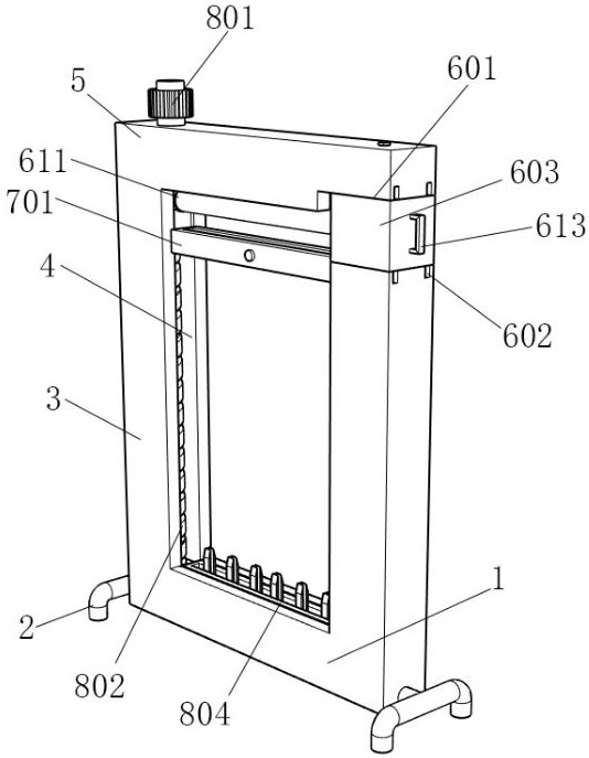
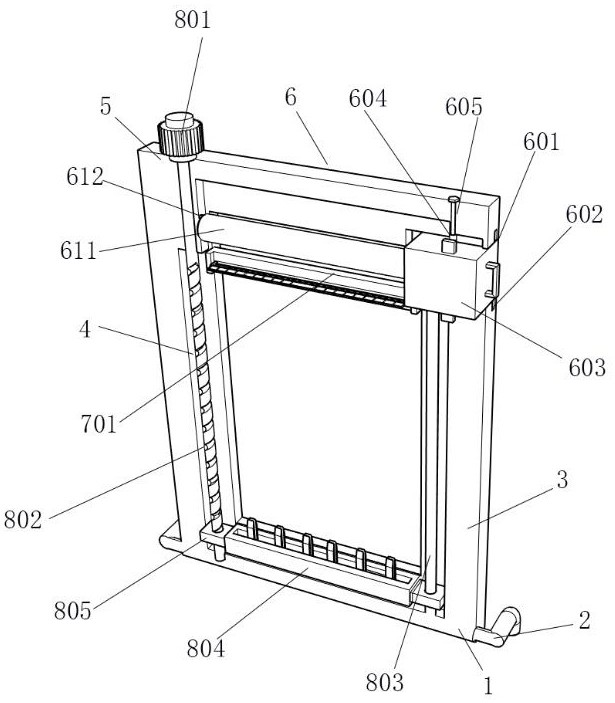
[0028] Embodiment one, by Figure 1-Figure 6 Given, the present invention comprises base plate 1, and support leg 2 is installed symmetrically on both sides of base plate 1, and side plate 3 is installed symmetrically on the top of base plate 1, and the side of two side plates 3 close to each other is provided with organic chute 4, and side plate The top of 3 is equipped with top plate 5, and the top of one of side plates 3 is equipped with discharging assembly 6, and cutting assembly 7 is installed between two side plates 3, and the inside of body chute 4 is equipped with pull-down assembly 8.

Embodiment 2

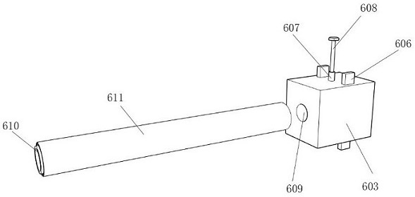
[0029] Embodiment 2, on the basis of Embodiment 1, the discharge assembly 6 includes a rotating groove 601 opened on the top of one of the side plates 3, and the top and bottom ends of the rotating groove 601 are symmetrically provided with limiting grooves 602, and the limiting grooves 602 Through to the outside of the side plate 3, a rotating block 603 is installed inside the rotating groove 601, and the top and bottom ends of the rotating block 603 are symmetrically installed with a limit block 606, and the limit block 606 is slidably connected to the inside of the limit groove 602. The top of 603 is equipped with sliding rotating rod 607, and sliding rotating rod 607 is slidably connected to the inside of top chute 604, and top chute 604 is offered at the bottom of top plate 5, and the top of sliding rotating rod 607 is threadedly connected with fixed screw rod 608, and fixed screw rod 608 is threadedly connected with the top screw groove 605, wherein the top screw groove 6...

Embodiment 3

[0031]Embodiment 3, on the basis of Embodiment 2, the cutting assembly 7 includes a fixed block 701 installed between the two side plates 3 , the inside of the fixed block 701 is provided with a through groove 702 , and the through groove 702 penetrates to the bottom of the fixed block 701 On the upper and lower sides, a cutting unit 703 is installed on the front of the through groove 702, and a cleaning unit 704 is installed on the back of the through groove 702. The cutting unit 703 includes a movable groove 7031 opened on the front of the through groove 702, and a movable plate is installed inside the movable groove 7031 7032, a cutting blade 7033 is installed on the back side of the movable plate 7032, an inner groove 7034 is provided on the back side of the movable plate 7032, and a spring 7036 is installed equidistantly inside the inner groove 7034, and one end of the spring 7036 is fixedly connected with the movable groove 7031, and the inner groove 7034 A magnetic block...


PUM


Abstract

The invention relates to the technical field of slitting equipment, and discloses an adhesive tape mother roll slitting device which solves the problem that when a cutter is used for cutting, mucilage glue is prone to adhering to the surface of the cutter, and consequently the cutter becomes blunt. The adhesive tape mother roll slitting device comprises a bottom plate, supporting legs are symmetrically installed on the two sides of the bottom plate, and side plates are symmetrically installed at the top end of the bottom plate; machine body sliding grooves are formed in the sides, close to each other, of the two side plates. A top plate is installed at the top ends of the side plates. In the working process, an output chain wheel of an arranged third motor drives a chain to move, bottom screw rods on the two sides are driven to get close to each other, clamping plates on the two sides clamp an adhesive tape roll, then an output shaft of a second motor rotates reversely, a moving block is driven to move downwards, and then the adhesive tape roll is rolled out; and at the moment, the second motor stops working to adapt to different slitting lengths, and meanwhile, the moving block drives the adhesive tape roll to stretch, so that the pull-down speed is increased, and the slitting efficiency is improved.

Description

technical field [0001] The invention belongs to the technical field of slitting equipment, in particular to a slitting device for an adhesive tape parent roll. Background technique [0002] Adhesive tape has become an indispensable stationery in people's daily life. Whether it is in a company or a family, it is used every day to paste envelopes, packaging or sealing boxes and other pasting purposes. Therefore, adhesive tape is used in daily life. It can be called a large number of consumables. At present, people use a general tape cutter when cutting the parent roll of adhesive tape. The design is more complicated and the production cost is higher. Although there are various tape cutters in the prior art , but the existing tape cutting machine can only be used to cut the tape of the same type of specification. [0003] Due to the high viscosity of the adhesive tape parent roll, when the cutter is cutting, the glue is easy to adhere to the surface of the cutter, causing the ...

Claims


Application Information

Patent Timeline
Patent Type & Authority Applications(China)
IPC IPC(8): B26D1/08B26D7/01B26D7/06B26D7/26
CPCY02E60/10
Inventor 陆雪江
Owner 扬州和创新材料科技有限公司
Learn More