Transformer

A transformer and magnetic core technology, applied in the field of transformers, can solve the problems of short axial winding length, many radial winding layers, and many radial layers, and achieve good anti-saturation ability, short winding circumference, The effect of reducing dosage

Active Publication Date: 2014-08-13
MIDEA GRP CO LTD +1
View PDF5 Cites 3 Cited by
  • Summary
  • Abstract
  • Description
  • Claims
  • Application Information

AI Technical Summary

Problems solved by technology

At the same time, since the primary winding 106 and the secondary winding 108 are configured coaxially and horizontally close to each other, in order to achieve good coupling between the primary winding 106 and the secondary winding 108, the number of radial turns of the primary winding 106 needs to be increased, and The number of axial turns is reduced, that is, the number of radial winding layers formed by the entire primary winding 106 is large, and the length of the axial winding is short; similarly, the number of radial turns of the secondary winding 108 needs to be increased, while the number of axial turns is reduced, That is to say, the entire secondary winding 108 has many radial winding layers and short axial winding length, which easily causes the problem of poor heat dissipation of the transformer
In addition, due to the large number of radial winding layers, more wire materials are required for the same number of winding coils, and the material cost is relatively large, and the number of radial layers of the primary winding 106 and the secondary winding 108 is large, which also increases The overall dimensions of the transformer 100

Method used


Image

  • Transformer
  • Transformer
  • Transformer

Examples


Embodiment approach 1

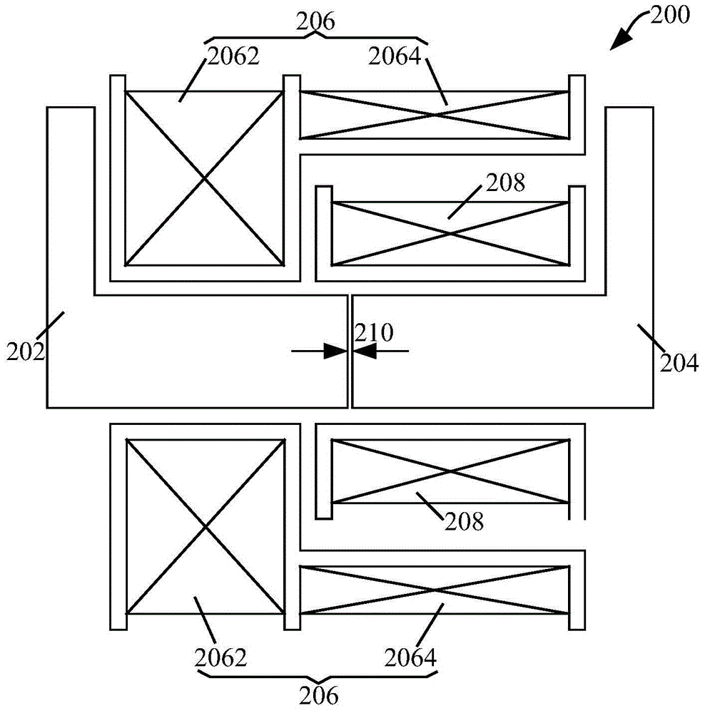
[0052] Such as Figure 3A As shown, the two magnetic cores include two L-shaped magnetic cores, that is, an L-shaped magnetic core 202 and an L-shaped magnetic core 204 , wherein one end of the L-shaped magnetic core 202 and one end of the L-shaped magnetic core 204 are placed opposite to each other.

Embodiment approach 2

[0054] Such as Figure 3B As shown, the two cores include an L-shaped core 302 and an I-shaped core 304 .

Embodiment approach 3

[0056] Such as Figure 3C As shown, the two cores include two T-shaped cores, T-shaped core 306 and T-shaped core 308 .

[0057] Certainly, when the closed magnetic core assembly is composed of a plurality of magnetic cores, there are also various implementations. Below, on the basis of the above-mentioned open magnetic core assembly, three structures of the closed magnetic core assembly are listed below.

[0058] Implementation Mode 1

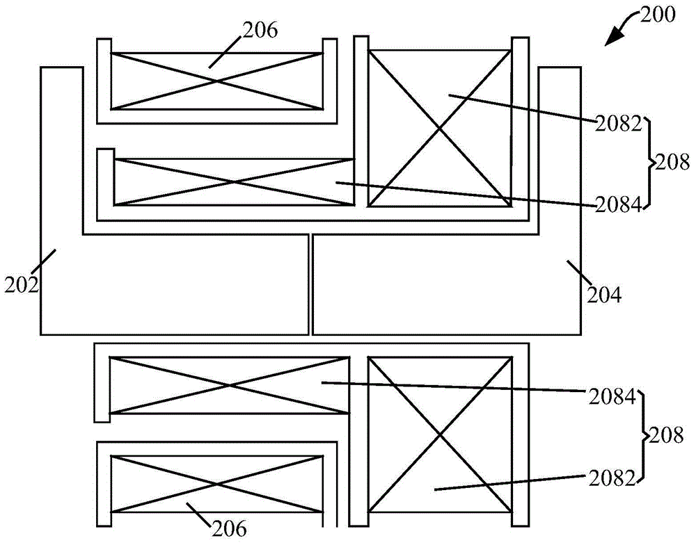
[0059] Such as Figure 4A shown in Figure 3A On the basis of the open-circuit magnetic core assembly shown, another magnetic core 402 is added to form a closed magnetic core assembly with the L-shaped magnetic core 202 and the L-shaped magnetic core 204 .

[0060] Implementation mode two

[0061] Such as Figure 4B shown in Figure 3B On the basis of the open-circuit magnetic core assembly shown, another magnetic core 404 is added to form a closed magnetic core assembly with the L-shaped magnetic core 302 and the I-shaped magnetic core ...


PUM


Abstract

The invention provides a transformer, which comprises a magnetic core assembly, a primary winding and a secondary winding, wherein the primary winding and the secondary winding are wound on the magnetic core assembly and are matched with the magnetic core assembly to be used, the primary winding comprises a first winding and a second winding, the first winding is coupled with the secondary winding in the axial direction, the second winding is coupled with the secondary winding in the radial direction, and/or the secondary winding comprises a third winding and a fourth winding, wherein the third winding is coupled with the primary winding in the axial direction, the fourth winding is coupled with the primary winding in the radial direction. Through the technical scheme of the transformer, the primary winding and the secondary winding in the transformer can be coupled in both the axial direction and the radial direction, in addition, the production cost of the transformer is reduced, and the heat radiation effect of the transformer is optimized.

Description

technical field [0001] The present invention relates to the technical field of transformers, in particular to a transformer. Background technique [0002] A high-frequency heating device such as a step-up transformer used in a magnetron drive is mainly composed of a winding shaft, a primary winding and a secondary winding arranged on the winding shaft, and at least two magnetic cores inserted into the winding shaft to form a magnetic circuit, such as Consists of two U-shaped cores or one U-shaped core and one I-shaped core. [0003] In the related art, the commonly used structure of the transformer is the primary winding, and the secondary winding is coaxially arranged on both sides of an insulator, and usually the primary winding and the secondary winding are arranged on the same arm of the U-shaped magnetic core. Above, this wire-wound magnetic core arm, another magnetic core arm, and the connection between the two arms form the magnetic circuit required for the transform...

Claims


Application Information

Patent Timeline
Patent Type & Authority Applications(China)
IPC IPC(8): H01F27/28H01F27/24H01F27/30
Inventor 陈华
Owner MIDEA GRP CO LTD
Why Eureka
Try Eureka