motor control unit

A control device and motor technology, applied in motor control, motor generator control, electronic commutation motor control, etc., can solve the problem of inability to obtain sufficient torque, inability to correctly calculate the limit torque value, inability to eliminate voltage saturation, etc. question

Active Publication Date: 2016-03-23
PANASONIC CORP
View PDF8 Cites 0 Cited by
  • Summary
  • Abstract
  • Description
  • Claims
  • Application Information

AI Technical Summary

Problems solved by technology

Therefore, the limit torque value τ cannot be accurately calculated when there are fluctuations in inductance due to operating conditions and variations in the motor constant of each motor. lmt *
[0013] When the limit torque value τ as the torque limit value due to this calculation error lmt *If it is set to a value larger than the actual limit torque, the current control will be performed based on the torque command τ* larger than the limit torque, and voltage saturation may not be eliminated.
[0014] In addition, conversely, at the limit torque value τ as the torque limit value lmt *If it is set to a value smaller than the actual limit torque, the torque command τ* will be excessively limited, and sufficient torque may not be obtained

Method used


Image

  • motor control unit
  • motor control unit
  • motor control unit

Examples


Embodiment approach 1

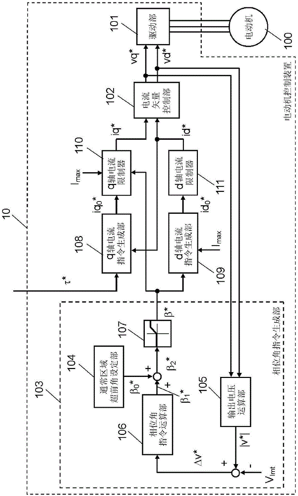
[0033] figure 1 It is a block diagram of the motor control device 10 in Embodiment 1 of this invention. The present motor control device 10 is constituted by a drive control system that drives a permanent magnet synchronous motor 100 in accordance with an external torque command τ*.

[0034] First, in figure 1Among them, the motor 100 has a permanent magnet (not shown) and a winding (not shown) wound around an iron core or the like. The rotor rotates by applying AC power to the winding from the motor control device 10 . exist figure 1 In , an example of the configuration in which the motor 100 is driven by three-phase AC power, which is a U phase, a V phase, and a W phase, is given.

[0035] Next, explain figure 1 The configuration and operation of each part of the present motor control device 10 are shown.

[0036] The drive unit 101 energizes and drives the windings of the motor 100 to rotationally drive the rotor. The drive unit 101 first performs a 2-phase-3-pha...

Embodiment approach 2

[0093] Figure 8 It is a block diagram of the motor control device 20 in Embodiment 2 of this invention.

[0094] This embodiment is constituted in figure 1 A filter 200 is further inserted in the preceding stage of the q-axis current command generator 108 in the first embodiment shown. Other configurations are the same as those in Embodiment 1, and detailed descriptions of the same configuration elements are omitted.

[0095] The filter 200 smoothes the torque command τ* input from the outside as a target command value. The smoothing algorithm is not particularly limited, for example, a one-order lag low-pass filter. Smoothed torque command τ LPF * is input to the q-axis current command generator 108 .

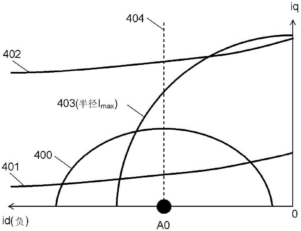
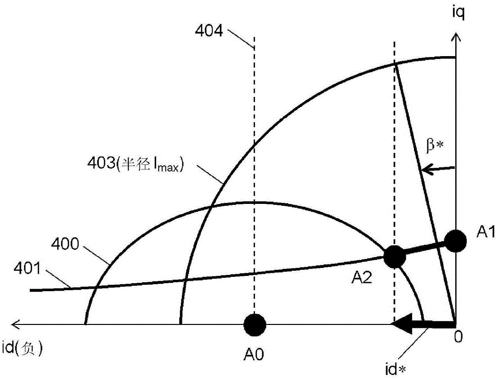
[0096] use Figure 9 The function and effect of the filter 200 are illustrated by the current vector locus of the filter 200. exist Figure 9 A voltage limit ellipse 900 , a constant torque curve 901 of an external torque command, a current limit circle 902 and a d-a...

Embodiment approach 3

[0105] Figure 10 It is a block diagram of the motor control device 30 in Embodiment 3 of this invention.

[0106] This embodiment is transformed into Figure 10 The structure shown in the phase angle command generator 300 is replaced by figure 1 An embodiment of the phase angle command generator 103 in Embodiment 1 is shown. Other configurations are the same as those in Embodiment 1, and detailed descriptions of the same configuration elements are omitted.

[0107] Figure 10 The phase angle command generating unit 300 in the above uses the q-axis component vq* of the voltage command instead of the absolute value |v*| of the voltage command in the first embodiment. In addition, the reference voltage correction unit 301 adjusts the predetermined reference value V lmt Make corrections. Then, from the corrected reference value vq lmt The difference Δvq* obtained by subtracting the d-axis component vq* is output to the phase angle command calculation unit 106 .

[0108] ...


PUM


Abstract

A current vector control unit is provided for controlling a current of the motor by separating it into orthogonal d-axis current and q-axis current according to a target command value, and the drive unit drives the motor. Then, the phase angle command generating unit generates a phase angle command (β*| ). The d-axis current command generator generates a d-axis current command (id*) based on the sine value of the phase angle command (β*). The q-axis current limiter sets the limit value of the q-axis current command (iq*) based on the cosine value of the phase angle command (β*). With this configuration, voltage saturation is eliminated, and even when a target command value exceeding the limit that the motor can output is input near voltage saturation, the motor is driven with high stability and high output.

Description

technical field [0001] The present invention relates to a motor control device using current vector control, and in particular to a technique for performing field weakening control and command limitation so as to make the motor perform electric running (Japanese: 力行) or regenerative operation near the voltage saturation region. Background technique [0002] In general, as a method of controlling the current of a permanent magnet synchronous motor, vector control is used in which the motor current is separated into a q-axis current contributing to torque and a d-axis component orthogonal thereto. A vector control unit that performs vector control receives an external command and calculates a command voltage for a motor drive unit that supplies electric power to the motor. [0003] In such vector control, there is a phenomenon that, for example, when the value of an external command becomes large, the command voltage exceeds the voltage that can be supplied by the motor drive ...

Claims


Application Information

Patent Timeline
Patent Type & Authority Patents(China)
IPC IPC(8): H02P21/22H02P21/06
CPCH02P21/0003H02P21/0089H02P21/06H02P2207/05H02P21/22
Inventor 佐佐木隆太岸本宪一
Owner PANASONIC CORP
Why Eureka
Try Eureka