Rotary angle-wrapping forming stamping die

A stamping die and angle wrapping technology, which is applied in the field of structural improvement of stamping dies, can solve problems such as low production efficiency, complex structure, and difficult control, and achieve the effects of reducing maintenance costs, improving production efficiency, and shortening the molding cycle

Active Publication Date: 2014-08-20
QINGDAO HISENSE MOLD
View PDF6 Cites 10 Cited by
  • Summary
  • Abstract
  • Description
  • Claims
  • Application Information

AI Technical Summary

Problems solved by technology

[0005] The invention proposes a rotary angle-wrap forming stamping die, which can solve the problems of the prior art that adopts

Method used


Image

  • Rotary angle-wrapping forming stamping die
  • Rotary angle-wrapping forming stamping die
  • Rotary angle-wrapping forming stamping die

Examples


Embodiment 1

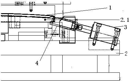
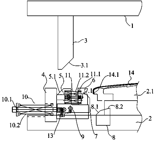
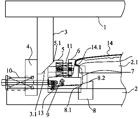
[0023] refer to Figure 2 to Figure 5 , the present embodiment takes the rotary corner forming of the refrigerator door shell 14 as an example. The parts 14.1 are one-to-one corresponding to the angle wrapping forming mechanism. The refrigerator door shell 14 is placed on the lower mold plate 2.1 on the lower mold base 2. The angle wrapping forming mechanism includes a side pusher assembly and a rotating angle wrapping forming assembly. The side push assembly includes a push rod 3, a push rod limit block 4, a slider seat 5, a binder plate 6 and an elastic reset part 10 of the slider seat, one end of the push rod 3 is fixed on the upper mold base 1, and the push rod limit block 4 is fixed on the lower die base 2 to limit the push rod 3 and the slider base 5; the slider base 5 is slidably installed on the lower die base 2, and the binder plate 6 is arranged on the slider base 5 and The block seat 5 is connected as a whole through the elastic part 11. The function of the pressin...

Embodiment 2

[0027] During the molding process, the guiding slope of the top block 8 plays the role of driving the pendulum block 7 to generate rotational movement. In this embodiment, the guiding slope includes two slopes with different inclination angles, which are connected up and down, and the slope angle of the lower slope 8.1 is greater than The inclination angle of the upper slope 8.2, the slope angle of the bottom slope 8.1 is advisable with 30-60 ° (in this embodiment, its slope angle is 45 °), the slope angle of the top slope 8.2 is advisable with 10-20 ° (in this embodiment Among them, the inclination angle is 15°). During the sliding process of the pendulum block 7 along with the slider seat 5, the lower slope 8.1 first comes into contact with, and its inclination angle is relatively large to make the pendulum block 7 quickly turn up and rotate to form an angle, and improve the forming efficiency. When the pendulum block 7 moves to When the lower slope 8.1 connects with the upp...


PUM


Abstract

The invention provides a rotary angle-wrapping forming stamping die. The rotary angle-wrapping forming stamping die can solve the problems that according to the prior art, an oil cylinder lateral thrusting forming mechanism is used for forming, the control difficulty is large, production efficiency is low, and the structure is complex. The rotary angle-wrapping stamping die comprises an upper die base, a lower die base and an angle-wrapping forming mechanism. The angle-wrapping forming mechanism comprises a lateral thrusting assembly and a rotary angle-wrapping forming assembly; the lateral thrusting assembly comprises a push rod, a push rod limiting block, a sliding block base, a pressure plate and a sliding block base elastic reset component. The rotary angle-wrapping forming assembly comprises a rotatable swinging block and an ejector block and the swinging block is of a forming structure. The ejector block is fixedly arranged on the lower die base and the side face, facing the side face of the swinging block, of the ejector block is a guiding slope. According to the rotary angle-wrapping forming stamping die, rotary angle-wrapping forming operation is in linkage with die closing operation, the forming cycle is shortened, and the production efficiency is greatly improved; the problem that due to the fact that the rotary angle-wrapping forming operation and the die closing operation are independent, if signal transmission and execution of the rotary angle-wrapping forming operation and the die closing operation are false, an angle-wrapping forming punch is prone to breakage is solved, and the maintenance cost of the die is reduced.

Description

technical field [0001] The invention relates to a stamping die, in particular to the improvement of the structure of the stamping die used for corner wrapping of stamping products. Background technique [0002] Appearance products, such as refrigerator door shells, washing machine shells, etc., have very strict appearance and size requirements. In order to achieve good appearance and precise size requirements, a set of molds are usually used for straight edge bending and corner forming. Avoid factors that affect product appearance and size such as cumulative errors caused by replacing different molds. [0003] In the prior art, corner wrapping is formed by an oil cylinder side pushing molding mechanism arranged in the mold, the product 1 is placed on the lower template 2.1 of the lower mold base 2, and an oil cylinder 3 is arranged at its corner wrapping position, and the oil cylinder 3 is installed On the lower mold base 2, the angle-wrapping punch 4 is driven by the oil c...

Claims


Application Information

Patent Timeline
IPC IPC(8): B21D11/10B21D37/10B21D37/12
Inventor 陈东崔得林秦根
Owner QINGDAO HISENSE MOLD
Why Eureka
Try Eureka