The structure of the pressure cylinder driving the double-ended collet in the main shaft

A pressure cylinder and spindle technology, which is applied in the field of machine tools, can solve the problems of large axial size of the spindle, laborious tightening methods, and increased manufacturing costs, and achieve the effects of increasing the range of workpieces to be processed, firm locking, and improving machining accuracy

Active Publication Date: 2018-12-11
浙江中智鲸工智能装备有限公司
View PDF7 Cites 0 Cited by
  • Summary
  • Abstract
  • Description
  • Claims
  • Application Information

AI Technical Summary

Problems solved by technology

[0002] Basically, the machine tool is equipped with a clamping device or a fixing device for fixing the workpiece. The simplest clamping device is a manually controlled elastic chuck installed on the spindle. The elastic chuck clamps the workpiece by manual tension. This tightening method is more laborious and easy to loosen; there are also cylinders or hydraulic cylinders to drive the collet to work, but it is basically used on the single-head collet, and it is set at one end of the single-head collet, resulting in the main shaft. The required axial dimension is relatively large, the range of processing workpieces is limited, and the required space is also relatively large. The additional hydraulic device or cylinder increases the manufacturing cost

Method used


Image

  • The structure of the pressure cylinder driving the double-ended collet in the main shaft
  • The structure of the pressure cylinder driving the double-ended collet in the main shaft
  • The structure of the pressure cylinder driving the double-ended collet in the main shaft

Examples


Embodiment Construction

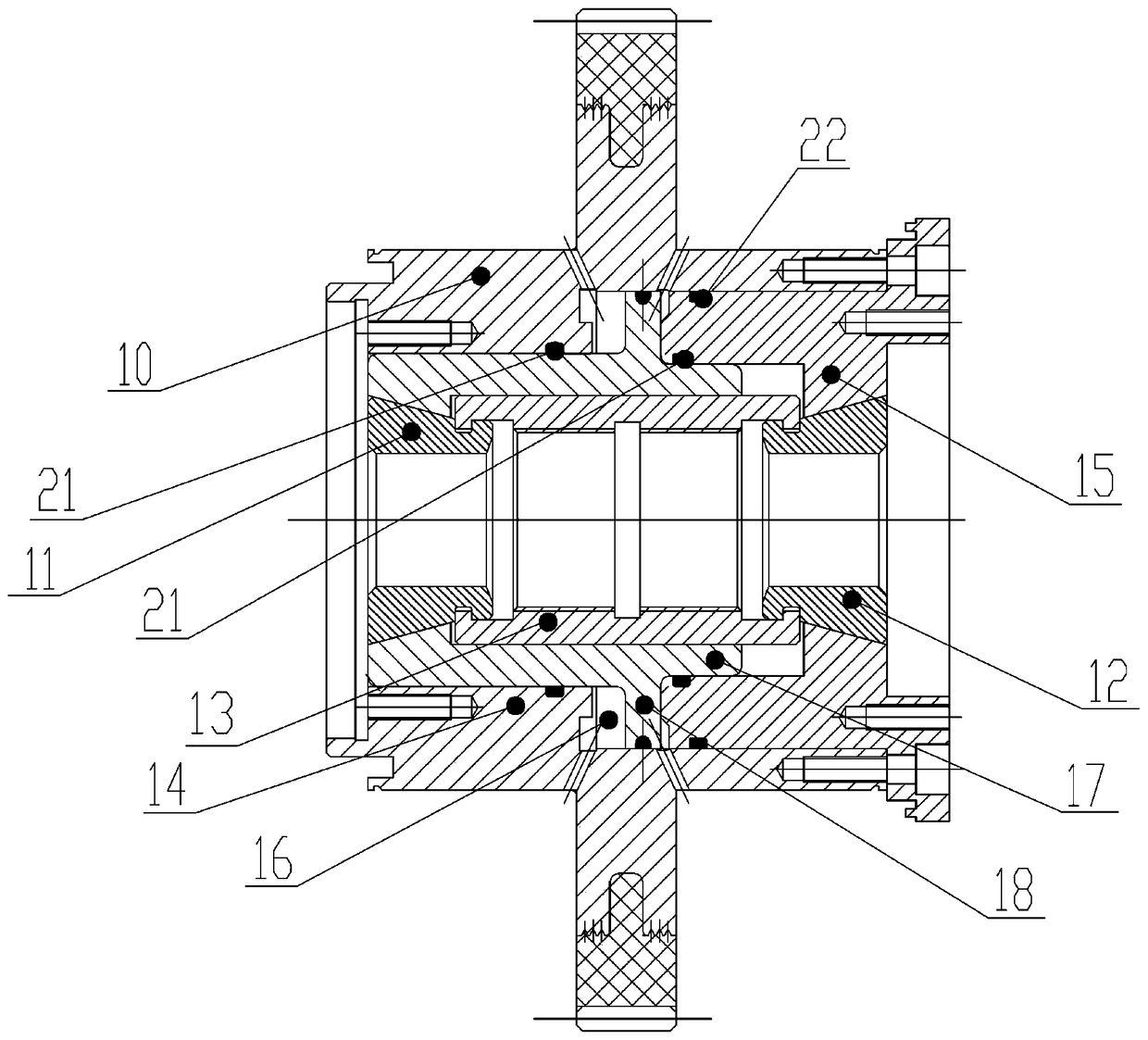
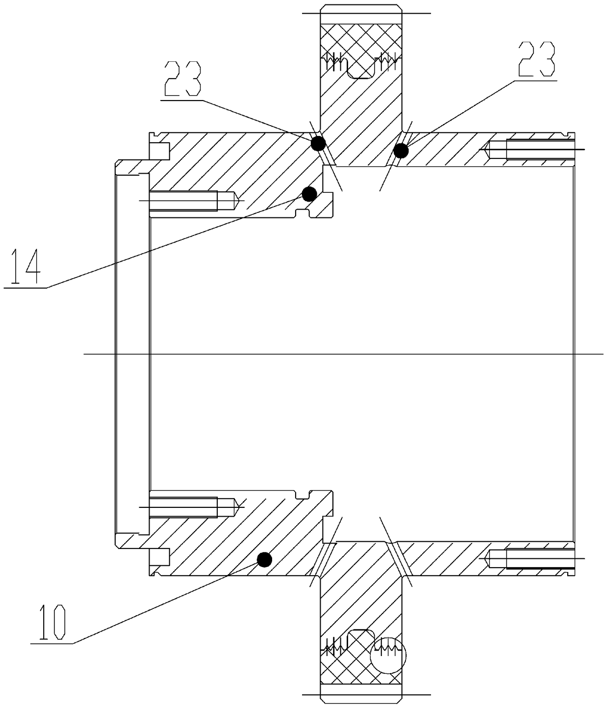
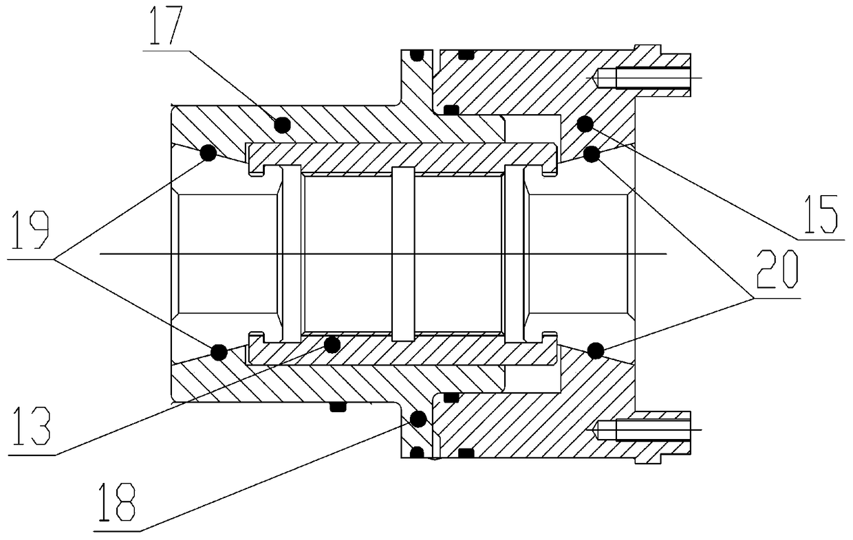
[0016] Below in conjunction with accompanying drawing, the present invention will be further described with specific embodiment, see figure 1 —3: The pressure cylinder structure driving the double-head collet in the main shaft, including the main shaft 10 and the collet I11 and the collet II12 arranged between the inner wall of the main shaft 10 and the drawing tube, and the collet I11 and the collet II12 are clamped on The two ends of the pull tube 13, wherein, the inner wall of one end of the main shaft 10 is provided with a limit ring 14, the limit ring 14 is located at the same end of the main shaft 10 as the collet I11, the limit ring 14 is raised, and its aperture is smaller than The aperture of the main shaft 10 is stepped, and the inner wall of the other end is provided with a cylinder cover 15, and the cylinder cover 15 is inserted into the hole of the main shaft 10, and a piston assembly is arranged between the limit ring 14 and the cylinder cover 15. The combined sp...


PUM


Abstract

The invention relates to a pressure cylinder structure for driving a double-head collet in a spindle and belongs to the technical field of machine tools. The pressure cylinder structure comprises the spindle, a collet I and a collet II, wherein the collet I and the collet II are arranged between the inner wall of the spindle and a stay tube and clamped at two ends of the stay tube. A limit ring is arranged on the inner wall at one end of the spindle, the limit ring and the collet I are arranged at the same end of the spindle, and a cylinder cover is arranged on the inner wall at the other end of the spindle. A piston assembly is arranged between the limit ring and the cylinder cover, the limit ring, the cylinder cover and the piston assembly form a pressure cylinder, and the piston assembly is sleeved with the collet I and the stay tube. By means of the characteristics of the structure of the spindle, the formed pressure cylinder is novel in structure, manufacturing materials are saved, the number of parts is decreased, spatial arrangement is reasonable, the outline is narrowed, the axial dimension of the spindle is shortened greatly, and the machining range of workpieces is enlarged. Furthermore, in the aspect of power, stable and smooth output can be achieved by means of the compact structural relationship, locking is firm, axial precision is high, and machining precision of products is improved.

Description

technical field [0001] The invention belongs to the technical field of machine tools, and relates to a workpiece clamping device on a machine tool main shaft, in particular to a pressure cylinder structure for driving a double-headed collet in the main shaft. Background technique [0002] Basically, the machine tool is equipped with a clamping device or a fixing device for fixing the workpiece. The simplest clamping device is a manually controlled elastic chuck installed on the spindle. The elastic chuck clamps the workpiece by manual tension. This tightening method is more laborious and easy to loosen; there are also cylinders or hydraulic cylinders to drive the collet to work, but it is basically used on the single-head collet, and it is set at one end of the single-head collet, resulting in the main shaft. The required axial dimension is relatively large, the range of processed workpieces is limited, and the required space is also relatively large. The additional hydrauli...

Claims


Application Information

Patent Timeline
Patent Type & Authority Patents(China)
IPC IPC(8): B23Q3/12F15B15/08F15B15/20
CPCB23Q3/12B23Q2703/04F15B15/14F15B15/1438F15B15/1442F15B15/1447
Inventor 赵亚飞杨荣
Owner 浙江中智鲸工智能装备有限公司
Why Eureka
Try Eureka