Valve gate injection mold

A technology for injection molds and sprue sleeves, which is applied in the field of valve gate injection molds, can solve the problems of gate casting, wire drawing, solidification, and affecting the quality of plastic parts, so as to reduce internal stress, reduce the chance of gate solidification, The effect of improving stability

Inactive Publication Date: 2014-08-20
KUNSHAN DAJIU ELECTRONICS
View PDF5 Cites 0 Cited by
  • Summary
  • Abstract
  • Description
  • Claims
  • Application Information

AI Technical Summary

Problems solved by technology

[0002] At present, when the existing hot runner is poured, the gate often has the phenomenon of casting, drawing, and solidification, which affects the quality of plastic parts

Method used


Image

  • Valve gate injection mold
  • Valve gate injection mold

Examples


Embodiment Construction

[0012] The present invention will be further described below in conjunction with the accompanying drawings.

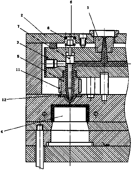
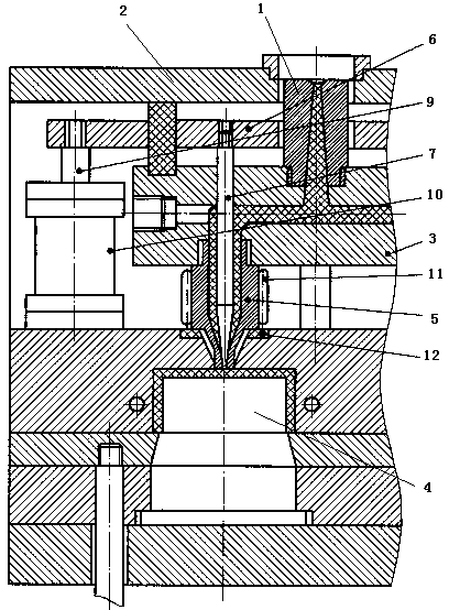
[0013] The first embodiment, such as figure 1 As shown, a valve gate injection mold includes a gate sleeve 1, a seat plate 2, a hot runner plate 3, a core 4, a nozzle 5, a probe seat plate 6, a needle valve 7, and a spring 8, The upper end of the seat plate 2 is provided with a sprue sleeve 1, and the lower end of the sprue sleeve 1 communicates with the hot runner plate 3; the outlet of the hot runner plate 3 is provided with a nozzle 5; the nozzle 5 is provided with a needle valve 7 , the top of the needle valve 7 is set at the outlet of the nozzle 5 , the end of the needle valve 7 is connected to one end of the spring 8 , and the other end of the spring 8 is connected to the probe seat plate 6 . An electric heating ring 11 is also included, and the electric heating ring 11 is arranged outside the side wall of the nozzle 5 . It also includes a thermal insulation pa...


PUM


Abstract

The invention discloses a valve gate injection mold including a fixed seat plate, a sprue bush, a hot runner plate, a mold core and a nozzle and also including a probe seat plate, a needle valve and a spring; the upper end of the fixed seat plate is provided with the sprue bush, and the lower end of the sprue bush is communicated with the hot runner plate; an outlet of the hot runner plate is provided with the nozzle; the nozzle is internally provided with the needle valve, the top end of the needle valve is arranged at an outlet of the nozzle, the tail end of the needle valve is connected with one end of the spring, and the other end of the spring is connected with the probe seat plate. The valve gate injection mold provided by the invention adopts a valve gate; and a reactive force generated by a high-pressure molten material is utilized to open the needle valve, then the spring or the power of a hydraulic cylinder is utilized to close the gate, tape casting and molten material wire drawing can be avoided, a gate solidification opportunity is reduced, internal stress of a molded part can be reduced, the stability of the molded part size is improved, and no gate marks are left on the molded part.

Description

technical field [0001] The invention relates to a valve gate injection mold, which belongs to the technical field of injection molds. Background technique [0002] At present, during the pouring of the existing hot runner, the phenomenon of casting, drawing, and solidification often occurs at the gate, which affects the quality of the plastic part. Contents of the invention [0003] Purpose: In order to overcome the deficiencies in the prior art, the present invention provides a valve gate injection mold. [0004] Technical solution: In order to solve the above-mentioned technical problems, the technical solution adopted in the present invention is: [0005] A valve-type gate injection mold, including a seat plate, a gate sleeve, a hot runner plate, a core, a nozzle, and a probe seat plate, a needle valve, and a spring, and a gate sleeve is arranged on the top of the seat plate , the lower end of the sprue sleeve communicates with the hot runner plate; a nozzle is arrang...

Claims


Application Information

Patent Timeline
IPC IPC(8): B29C45/28
CPCB29C45/2806
Inventor 王枫
Owner KUNSHAN DAJIU ELECTRONICS
Why Eureka
Try Eureka