Can conveying device

A technology of can feeding and conveying chain, applied in the field of can filling and capping production line, can solve the problems of severe material spillage, track wear, and large friction between the material tank and the guide rail of the conveying tank, and achieves wide applicability, small contact surface, Reduce the effect of material spillage

Active Publication Date: 2014-08-20
南京轻机包装机械有限公司
View PDF5 Cites 4 Cited by
  • Summary
  • Abstract
  • Description
  • Claims
  • Application Information

AI Technical Summary

Problems solved by technology

[0003] In order to solve the problem that the material tank and the guide rail of the tank conveying have a large friction force in the existing tank conveying device, resulti

Method used


Image

  • Can conveying device
  • Can conveying device
  • Can conveying device

Examples


Embodiment Construction

[0015] The present invention will be further described below in conjunction with accompanying drawing.

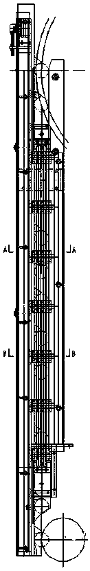
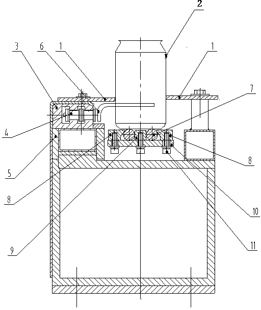
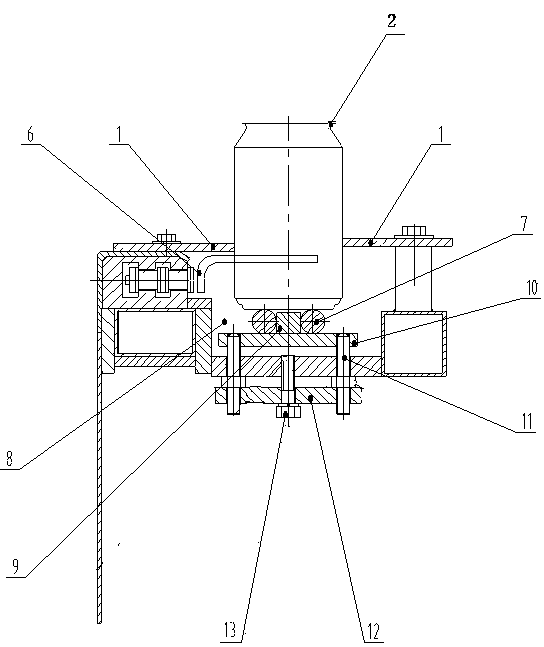
[0016] The top view when the present invention is applied to the can filling and capping production line is as follows figure 1 As shown, the device is installed between the filling machine and the capping machine, and includes the can conveying platform support 5 and the can conveying guide rail, the conveying chain guide rail 3 is arranged inside the can conveying platform support 5, and the conveying chain 4 is inside the conveying chain guide rail 3 The movement of the conveying chain 4 is connected with a claw 6, and the material tank 2 is driven by the claw 6 to move along the upper surface of the tank transport rail. The two sides of the material tank 2 are provided with a tank guard plate 1, which is characterized in that: the tank transport The guide rail includes a support plate 10 and several round steel guide rails 7 fixed on the support plate.

[0017] The rou...


PUM


Abstract

The invention provides a can conveying device which is applicable to conveying various ring-pull cans between a filling machine and a capping machine. The can conveying device comprises a can conveying table support and a can conveying guide rail. A conveying chain guide rail with a conveying chain is arranged in the can conveying table support. A conveying chain is connected with a shifting pawl, a ring-pull can is driven by the shifting pawl to move along the upper surface of the can conveying guide rail, can protection plates are arranged on the two sides of the ring-pull can, and the can conveying guide rail comprises a supporting plate and a plurality of round steel guide rails fixed to the supporting plate. According to the can conveying device, the round steel guide rails replace traditional nylon plates or stainless steel plates, the contact face between the can bottom and the guide rails is small, the friction force is small, the phenomenon that materials are spilled is reduced, the round steel guide rails rotating by an angle can be used again after one sides of the round steel guide rails are abraded, and the service life is long; the height and interval of the round steel guide rails can be adjusted, and requirement for filling and conveying different ring-pull cans can be met, and applicability is good.

Description

technical field [0001] The invention relates to the field of pop can filling and capping production line, in particular to a can feeding device. Background technique [0002] The stability of can transportation between filling and capping machines in the can filling production line affects the liquid level in the can after filling, thus affecting the qualified rate of finished products and the can and cap damage rate of the production line. The most important reason for the instability of can delivery is the flatness and surface smoothness of the can delivery guide rail. Conventional guide rails are made of nylon or stainless steel plates. It is difficult to guarantee the flatness and surface finish of the processed parts. The bottom of the tank and the guide rail are in surface contact, so the friction force is large, the tank is prone to shaking, and the surface of the rail is easy to wear. It can barely adapt to the line below 18000bph, but the high-speed line causes...

Claims


Application Information

Patent Timeline
IPC IPC(8): B65G21/22B65G17/18
Inventor 顾建新王佺王晓冬曾勇陈根明
Owner 南京轻机包装机械有限公司
Why Eureka
Try Eureka