Elevator speed governor

An elevator speed limiter and speed limiter technology, which is applied in the direction of elevators, transportation and packaging, etc., can solve the problems of affecting the locking effect of safety gear and guide rail, unfavorable manufacturing, installation, and effect effects, etc., to achieve ideal operation reliability, Facilitate manufacturing and improve friction

Active Publication Date: 2014-08-20
SUZHOU LAIYIN ELEVATOR CO LTD
View PDF11 Cites 16 Cited by
  • Summary
  • Abstract
  • Description
  • Claims
  • Application Information

AI Technical Summary

Problems solved by technology

But there is the shortcoming that the frictional force between the traction rope and the overspeed governor wheel (this patent is called the sheave) is small as described in CN1330030A, and there is a gap between negative rotation in the process that the overspeed governor wheel rotates with the elevator car lifting and lowering. Yu
[0006] Furthermore, as the invention patent application publication number CN101979299A discloses "a kind of elevator speed limiter", the patent application scheme avoids the slipping of the elevator car after stopping by adding a set of safety devices, specifically, through the additional installation device Make the traction rope (the patent application is called the speed limiter steel wire rope) in a tensioned state, but there is a technical problem of taking care of one thing and losing the other. Due to the action of gravity, the traction rope winding around the speed governor sheave and the tensioning sheave is in a tensioned state. Once the car slips, the traction rope in the tensioned state will be moved with it. Under the action of friction between the speed limiter sheave or the tensioner sheave, the safety gear is driven by the traction rope to prevent the elevator car from slipping
The so-called loss, because the tensioning sheave is far away from the speed governor sheave of the speed limiter, and an additional mounting seat is required for the tensioning sheave, so that the tensioning sheave is rotatably arranged on the mounting seat, thus The structure is relatively loose, which is not conducive to manufacturing and installation
And because the weight is not connected with the traction rope, but is located under the tensioning sheave, the action of the weight on the traction rope is indirect, and its effect is affected to a certain extent.
[0007] The applicant believes that if one end of the traction rope that is connected to the elevator car frame and the other end is connected to the weight (that is, the counterweight) can always be kept in good contact with the overspeed governor wheel, that is, the distance between the traction rope and the speed limiter can be increased. If the wrap angle between the speed limiter wheels can be ensured, the traction rope can drive the speed limiter wheel with excellent friction when running with the car, so as to avoid the negative rotation of the speed limiter wheel, and thus ensure the The centrifugal hammer as the structural system of the centrifugal mechanism triggers the lock in time, and the lock releases the locking of the lifting mechanism of the installation tongs, so that the lifting mechanism of the safety gear drives the action of the safety gear; the applicant also believes that the prior art Connecting one end of the traction rope to the safety gear does not have the effect of continuously exerting a good pulling force on the safety gear, which affects the locking effect of the safety gear and the guide rail

Method used


Image

  • Elevator speed governor
  • Elevator speed governor
  • Elevator speed governor

Examples


Embodiment Construction

[0027] In order to enable the examiners of the patent office, especially the public, to understand the technical essence and beneficial effects of the present invention more clearly, the applicant will describe in detail the following in the form of examples, but none of the descriptions to the examples is an explanation of the solutions of the present invention. Any equivalent transformation made according to the concept of the present invention which is merely formal but not substantive shall be regarded as the scope of the technical solution of the present invention.

[0028] In the following descriptions, all concepts involving up, down, left, right, front and rear directionality (or orientation) are for the position state of the picture being described, and the purpose is to facilitate the public Therefore, it cannot be understood as a special limitation on the technical solution provided by the present invention.

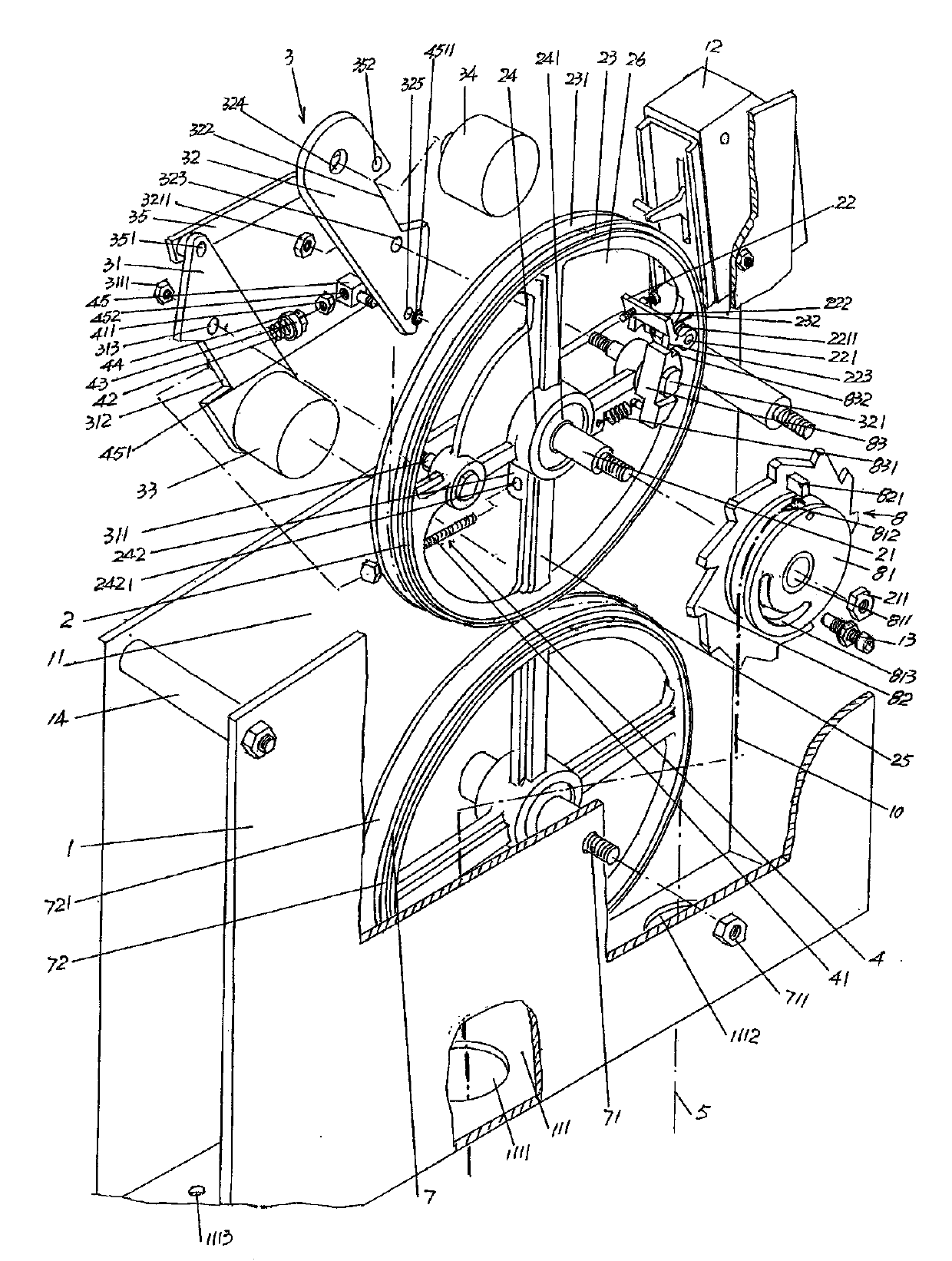
[0029] See figure 1 , provides a box body 1, and this b...


PUM


Abstract

The invention discloses an elevator speed governor, and belongs to the technical field of elevator safety protection devices. The elevator speed governor comprises a box body which is provided with a signal collector, a speed governor wheel which is provided with a lock catch, a centrifugal mechanism which is arranged on the speed governor wheel, a centrifugal hammer reset mechanism which is arranged on the speed governor wheel and connected with the centrifugal mechanism, and a traction rope with the upper end fixed to an upper end and lower end connecting counter weight of a top layer floor. The elevator speed governor is characterized by further comprising a traction rope pressing wheel, a safety tongs braking rope and a braking rope traction mechanism, the traction rope pressing wheel is located in a cavity of the box body and arranged in the middle of a traction rope pressing wheel shaft, the middle of the traction rope is wound on the speed governor wheel and the traction rope pressing wheel, the upper end of the safety tongs braking rope is tied and fixed to the braking rope traction mechanism, the lower end of the safety tongs braking rope is connected with a pair of safety tongs, the speed governor wheel shaft is sleeved with the braking rope traction mechanism, and the braking rope traction mechanism is matched with the signal collector and the lock catch. The situation that negative rotation happens to the speed governor wheel is avoided; the effect of reliably locking a guide rail through the safety tongs is improved; action is reliable, and safety is ensured; the structure is simple, manufacturing is convenient, and assembling is rapid.

Description

technical field [0001] The invention belongs to the technical field of elevator safety protection devices, and in particular relates to an elevator speed governor. Background technique [0002] The elevator speed limiter is a safety protection device used to control the overspeed running (running) of the elevator car. It is usually installed in the machine room. When the elevator overspeed reaches the speed value of the elevator speed limiter, the safety switch of the elevator speed limiter (The industry is accustomed to call it the overspeed switch) action, the control circuit is disconnected by the safety switch (that is, the signal collector, the same below), and the elevator stops running. At the same time, the wire rope of the speed governor pulls the traction rod (also called the connecting rod) of the safety gear with the help of the friction of the speed governor wheel to make the safety gear move, and the safety gear clamps the guide rail to make the elevator car st...

Claims


Application Information

Patent Timeline
Patent Type & Authority Applications(China)
IPC IPC(8): B66B5/24
Inventor 蒋黎明李云波万少帝
Owner SUZHOU LAIYIN ELEVATOR CO LTD
Why Eureka
Try Eureka