Optical cable splice box

A technology of optical cable joint box and box body, which is applied in the direction of fiber mechanical structure, etc., can solve the problems of sealing effect influence, sealing ring instability, low precision requirements, etc., and achieve the effects of cost saving, good sealing performance and high overall strength

Active Publication Date: 2014-08-20
杭州华宏通信设备有限公司
View PDF5 Cites 14 Cited by
  • Summary
  • Abstract
  • Description
  • Claims
  • Application Information

AI Technical Summary

Problems solved by technology

[0003] The present invention is to overcome the problem that the ordinary sealing structure used in the optical cable splice box in the prior art, when the pressure is large and the heat is large, the sealing ring is prone to instability, displacement, overflow and other conditions, which will affect the sealing effect. , provides a joint box with good fit, low precision requirements, and can guarantee the sealing effect even under pressure and heat

Method used


Image

  • Optical cable splice box
  • Optical cable splice box
  • Optical cable splice box

Examples


Embodiment 1

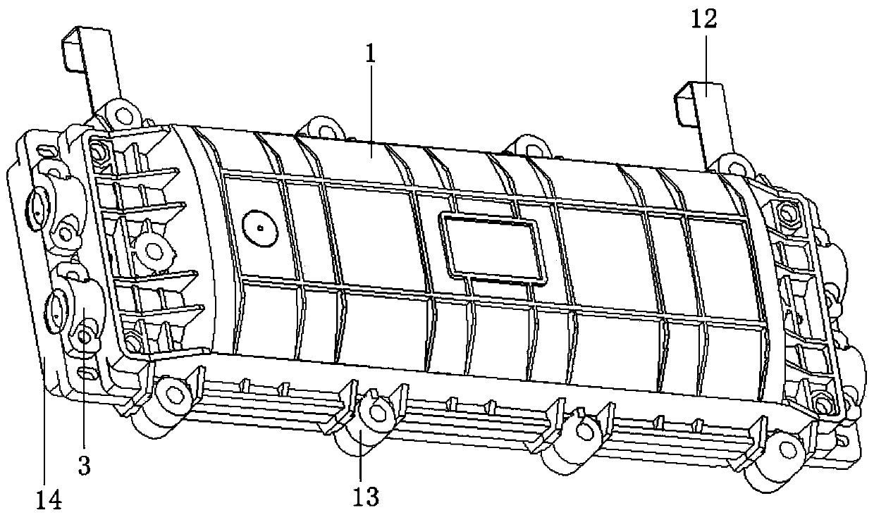
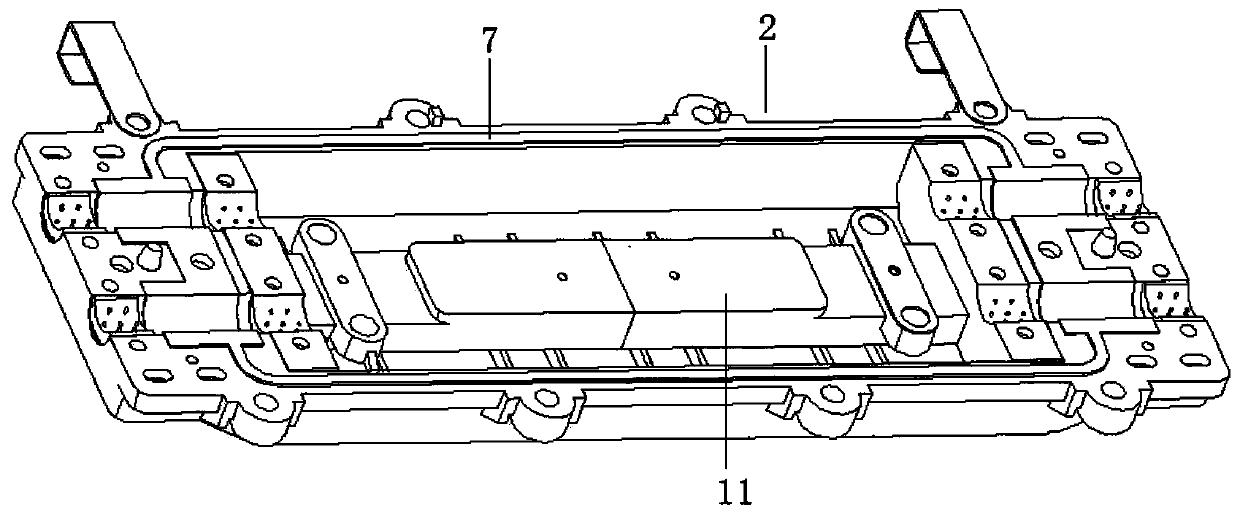
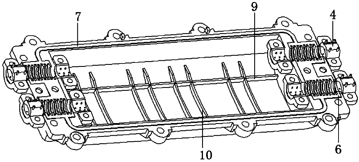
[0024] Such as figure 1 , figure 2 , image 3 , Figure 4 , Figure 6 , Figure 7In the shown embodiment, an optical cable splice box includes an upper half box 1 and a lower half box 2, and the upper half box 1 and the lower half box 2 are connected by screws to form a box body, and the box body The two ends of the body are respectively provided with at least two optical fiber hole frames. The optical fiber hole frame includes an outer section and an inner section. The sealing part 3 is formed, the outer section is provided with an optical fiber inlet sleeve 4, and the optical fiber inlet sleeve 4 is provided with a number of raised position-limiting studs 5, and the inner section is formed by the lower half box 2. The half hole groove and the half hole groove on the upper half box 1 jointly constitute, and the elastic ferrule 6 corresponding to the half hole groove is provided in the described half hole groove, and the upper half box 1 and the lower half box 2 are all ...

Embodiment 2

[0027] In this embodiment, the basic structure and implementation mode are the same as in Embodiment 1, and the differences are as Figure 5 As shown in: the middle part of the big bottom edge of the sealing strip 7 is provided with a V-shaped groove 17, and the two inner sides of the V-shaped groove 17 are provided with tightening guide grooves 18, and the V-shaped groove 17, tightened The length and length direction of the guide groove 18 are consistent with the sealing strip 7 , and the two sides of the sealing strip 7 protrude outward to form an anti-overflow limiting portion 19 . In addition, since the two V-shaped grooves 17 jointly form a deformation space, a cylindrical support rod can be arranged in the deformation space, and the length direction of the support rod is the same as that of the V-shaped groove 17 .

[0028] When the two half-boxes are connected and compressed, the two sealing rings stick to each other and squeeze each other. If such a force is applied fo...


PUM


Abstract

The invention discloses an optical cable splice box, and aims at providing a splice box which is good in matching and low in accuracy requirement and can ensure a sealing effect during bearing and heating. The optical cable splice box comprises an upper half box and a lower half box, wherein the upper half box and the lower half box are connected to forma box body; at least two optical fiber hole frames are arranged at the two ends of the box body respectively; each optical fiber hole frame comprises an outer section and an inner section; optical fiber inlet sleeves are arranged in the outer sections; the inner sections consist of half slots in the lower half box and half slots in the upper half box; corresponding elastic clamp sleeves are arranged in the half slots; sealing grooves are formed in the upper half box and the lower half box; sealing strips are arranged in the sealing grooves; the sealing strips and the elastic clamp sleeves are connected to form sealing rings; each sealing strip is 0.5-1mm higher than an opening of each sealing groove; and cross sections of the sealing strips are trapezoids with outward large bottom edges. The optical cable splice box has the benefits that an assembling accuracy requirement is low; the cost is saved; displacement is not easy to generateat butting parts of the sealing rings; the sealability is good; and a reinforcing structure is arranged in the box body, so that the compressive capacity and the overall strength are high.

Description

technical field [0001] The invention belongs to the technical field of optical cable lines, in particular to an optical cable joint box. Background technique [0002] Optical cable splice box, also known as optical cable splice box, belongs to the mechanical pressure sealing joint system, which is a splice protection device that provides optical, sealing and mechanical strength continuity between adjacent optical cables. It is mainly suitable for straight-through and branch connections of overhead, pipeline, direct buried and other laying methods of optical cables of various structures. The optical cable splice box is mostly composed of two half boxes, with a sealing ring set between them, and an optical cable inlet or outlet hole at the end to achieve sealing, pressure resistance and impact resistance, and the entry and exit of the optical cable. However, in the sealing structure of the existing optical cable splice closure, the matching accuracy of the sealing ring and th...

Claims


Application Information

Patent Timeline
Patent Type & Authority Applications(China)
IPC IPC(8): G02B6/44
Inventor 巩少荧
Owner 杭州华宏通信设备有限公司
Why Eureka
Try Eureka