Automatic rotor chamfering machine

A technology of chamfering machine and rotor, applied in the direction of manufacturing stator/rotor body, etc., can solve the problems of high work intensity, low work efficiency, unstable quality, etc., and achieve the effect of reducing labor and improving work efficiency.

Active Publication Date: 2014-08-20
合肥凯邦电机有限公司
View PDF5 Cites 3 Cited by
  • Summary
  • Abstract
  • Description
  • Claims
  • Application Information

AI Technical Summary

Problems solved by technology

At present, a special lathe is used for chamfering, which requires manual operation by the operator. The work intensity is high, the quality is unstable, the work efficiency is low, and the production cost is high.

Method used


Image

  • Automatic rotor chamfering machine
  • Automatic rotor chamfering machine
  • Automatic rotor chamfering machine

Examples


Embodiment Construction

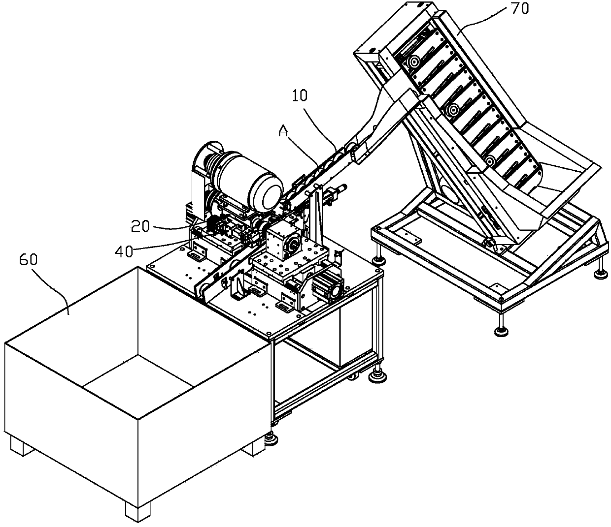
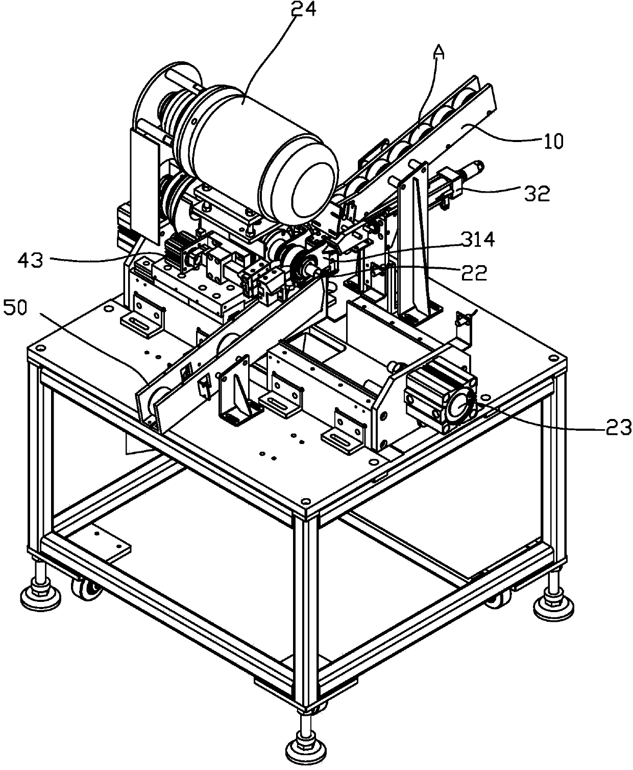
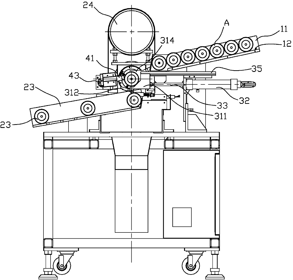
[0011] An automatic rotor chamfering machine, including a guide groove 10 arranged obliquely from top to bottom for the rolling guide of the rotor A, the lower end of the guide groove 10 is connected with a transfer mechanism 30, and the side of the transfer mechanism 30 There is a jig 20 that clamps the rotor A and drives it to rotate. The transfer mechanism 30 includes a U-shaped or V-shaped bayonet 31 that supports the rotor A, and a blanking port and a jig for driving the bayonet 31 in the guide groove 10 20, a cutting tool 40 for chamfering the rotor A is set beside the fixture 20. like figure 2 As shown, one end of the guide groove 10 is higher and the other end is lower, the high end of the guide groove 10 is connected to the automatic feeding device of the rotor, and the lower end of the feeding port corresponds to the position of the bayonet 31, ensuring that the rotor A can move from the guide groove 10 The blanking mouth of the roll rolls out and falls in the bayo...


PUM


Abstract

The invention relates to the field of motors, in particular to an automatic rotor chamfering machine. The automatic rotor chamfering machine comprises a guiding conveying groove arranged in an inclined mode from top to bottom. A rotor A is guided and conveyed in a rolling mode through the guiding conveying groove. A discharging opening in the lower end of the guiding conveying groove is connected with a transfer mechanism. A clamp which clamps the rotor A and drives the rotor A to rotate is arranged nearby the transfer mechanism. The transfer mechanism comprises a U-type or V-type clamping opening for supporting and being connected with the rotor A, and a driving mechanism for driving the clamping opening to move between the discharging opening of the guiding conveying groove and the clamp. A cutting tool for chamfering the rotor A is arranged nearby the clamp. The rotor rolls along the guiding conveying groove into the clamping opening. The transfer mechanism transfers the clamping opening to the clamping position of the clamp. The clamp clamps the rotor inside the clamping opening, and then the driving mechanism drives the rotor to rotate, so that the rotor and the cutting tool relatively rotate. The tool turns the end face of the rotor, and therefore the rotor is chamfered. According to the automatic rotor chamfering machine, in the chamfering process, the tool does not need to be manually operated, the amount of labor is greatly reduced, and working efficiency is improved.

Description

technical field [0001] The invention relates to the field of motors, in particular to an automatic rotor chamfering machine. Background technique [0002] The squirrel cage rotor consists of a cylindrical iron core made of circular silicon steel sheets and aluminum rings fixed at both ends of the iron core. The aluminum rings are pressed on the iron core by a die-casting mold. There are burrs and flashes on the cylindrical end surface of the rotor after die-casting. In order to remove the burrs and flashes, it is necessary to chamfer the cylindrical end surface of the rotor. At present, special-purpose lathes are used for chamfering, which requires manual operation by operators, which has high work intensity and unstable quality, low work efficiency and high production costs. Contents of the invention [0003] The purpose of the present invention is to provide a rotor automatic chamfering machine with high working efficiency and low production cost. [0004] In order to ...

Claims


Application Information

Patent Timeline
Patent Type & Authority Applications(China)
IPC IPC(8): H02K15/02
Inventor 黄宗
Owner 合肥凯邦电机有限公司
Why Eureka
Try Eureka